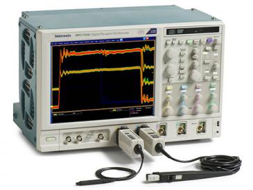
기기명 (Instrument) : Digitizing Oscilloscope (디지타이징 오실로스코프)
제작회사 (Manufacturer) : Tektronix (텍트로닉스)
형식 (Model) : TDS784D
세부내용 (Description) :
Features & Benefits
-. 1 GHz Bandwidth
-. Sample Rate to 4 GS/s
-. 200,000 Maximum Waveform Capture Rate
-. 4 Channels
-. 1% Vertical Accuracy
-. 8-Bit Vertical Resolution, Over 11 Bits with Averaging and Over 13 Bits with Hi-res
-. 1 ns Peak Detect
-. 1 mV/div to 10 V/div Sensitivity
-. Channel Deskew
-. Record Lengths to 8 M Points
-. Floppy Disk Storage
-. Iomega Zip and Zip Plus Drive Compatible
-. Advanced Triggering
-. 29 Automatic Measurements and Measurement Statistics
-. FFT and Advanced Math
-. Histograms
-. Histogram Statistics
-. Limit Test
-. FastFrame™ Time Stamp
-. Communication Signal Analysis Including Mask Testing and SONET/SDH and Fibre Channel Optical Reference Receivers
-. Full GPIB Programmability
-. 3 Year Warranty
-. CE Marking
Applications
-. Communication Compliance Testing
-. Digital Design and Debug
-. Jitter and Timing Analysis
-. Fast Edge Characterization
-. Video Design and Debug
-. Disk Drive Measurements
-. Power Measurements
Characteristics
TDS784D Electrical Characteristics
|
Max Real-time Sample Rate |
|
|
Maximum Record Length |
|
|
Bandwidth |
1 GHz*1 |
|
# Channels |
4 |
|
# Samplers |
4 |
|
1 channel |
4 GS/s |
|
2 channels |
2 GS/s |
|
3-4 channels |
1 GS/s |
|
Equivalent-time sample rate |
250 GS/s max. |
|
1 channel |
50 K (Opt. 1M: 500 K, Opt. 2M: 8 M) |
|
2 channels |
50 K (Opt. 1M: 250 K, Opt. 2M: 4 M) |
|
3-4 channels |
50 K (Opt. 1M: 130 K, Opt. 2M: 2 M) |
|
Max sample rate window*2 |
2 ms |
|
Display |
NuColorDisplay |
*1 In 50 Ω mode: 5 mV/div: 750 MHz, 2 mV/div: 600 MHz, 1 mV/div: 500 MHz. Reduce the upper bandwidth frequencies by 5 MHz for each degree C above 30 °C.
*2 Single-channel operating at full sample rate and maximum record length (Opt. 2M).
TDS784D Vertical System
|
Sensitivity |
1 mV/div to 10 V/div (1 MΩ mode), 1 mV/div to 1 V/div (50 Ω mode) |
|
DC gain accuracy |
±1.0% (±0.7% typical) |
|
Effective bits (typical) |
5.5 (1 GHz @ 4 GS/s), 9.7 with hi-res (1 MHz @ 10 MS/s) |
|
Vertical resolution |
8 Bits (256 levels on 10.25 divisions), >11 Bits with averaging, >12 Bits typical with hi-res |
|
Position range |
±5 divisions |
|
Offset range |
±1 V from 1 mV to 100 mV/div, ±10 V from 101 mV to 1 V/div, ±100 V from 1.01 V to 10 V/div |
|
Analog bandwidth selections |
20 MHz, 250 MHz, full |
|
Input coupling |
AC, DC, GND |
|
Input impedance selections |
1 MΩ in parallel with 10 pF or 50 Ω (AC and DC coupling) |
|
AC-coupled low frequency limit |
≤10 Hz when AC 1 MΩ coupled. ≤200 kHz when AC 50 Ω coupled. |
|
Channel isolation |
>100:1 at 100 MHz and >30:1 at the rated bandwidth |
|
Max. input voltage |
300 V CAT II ±400 V (peak). Derate at 20 dB/decade above 1 MHz. 1 MΩ or GND coupled. |
TDS784D Timebase System
|
Time bases |
Main, delayed |
|
Time base range |
200 ps to 10 s/div |
|
Time base accuracy |
±25 ppm (over any interval ≥1 ms) |
|
Delta time measurement accuracy |
±(0.15/sample rate) + (25 ppm x [reading]) |
|
Trigger jitter |
7 ps (typical) |
|
Pre-trigger position |
0% to 100% of any record |
|
Delay between channels |
≤50 ps (any 2 channels with equal V/div and coupling) |
Acquisition Modes
DPO - Captures and displays complex waveforms, random events and subtle patterns in actual signal behavior. By acquiring up to 100 M points/sec, the TDS784D DPO is able to provide 3 dimensions of signal information, in real-time; amplitude, time, and the distribution of amplitude over time. The DPX™ Waveform Imaging Processor automatically selects record lengths between 500 and 500,000 points and sample rate up to 1 GS/s, based on horizontal time base setting, to optimize displayed sample density.
Peak Detect - High frequency and random glitch capture. Captures glitches of 1 ns using acquisition hardware at all real-time sampling rates.
Sample - Sample data only.
Envelope - Max/min values acquired over one or more acquisitions.
Average - Waveform data from 2 to 10,000 (selectable) is averaged.
Hi-res - Vertical resolution improvement and noise reduction on low-frequency signal (e.g. 12 Bits typical).
FastFrame™ Time Stamp - Acquisition memory size segmentable with trigger rate up to 80,000 per second from 50 to 5,000 points per frame (independent of the number of channels).
Single Sequence - Use RUN/STOP button to capture a single triggered acquisition at a time, which may be automatically saved to NVRAM with AutoSave.
Trigger System
Triggers - Main and delayed.
Main Trigger Modes - Auto, normal, single.
Delayed Trigger - Delayed by time, events or events and time.
Time Delay Range - 16 ns to 250 s.
Events Delay Range - 1 to 9,999,999 events.
External Rear Input - ≥1.5 kΩ; Max input voltage is ±20 V (DC + peak AC).
Trigger Types
EDGE (main and delayed) - Conventional level-driven trigger. Positive or negative slope on any channel or rear panel auxiliary input. Coupling selections: DC, AC, noise reject, HF reject, LF reject.
LOGIC (main) - PATTERN: Specifies a logical combination (AND, OR, NAND, NOR) of the four input channels (high, low, don't care). Trigger when pattern stays true or false for a specified time.
STATE: Any logical pattern of channels 1, 2, and 3 (AUX1 on 2-CH products) plus a clock edge on channel 4 (AUX2 on 2-CH products). Triggerable on rising or falling clock edge.
SETUP/HOLD: Trigger on violations of both setup time and hold time between clock and data which are on two input channels.
PULSE (main) - GLITCH: Trigger on or reject glitches of positive, negative, or either polarity. Minimum glitch width is 1.0 ns (typical) 2 ns (warranted) with 200 ps resolution.
RUNT: Trigger on a pulse that crosses one threshold but fails to cross a second threshold before crossing the first again.
WIDTH: Trigger on width of positive or negative pulse either within or out of selectable time limits (1 ns to 1 s).
SLEW RATE: Trigger on pulse edge rates that are either faster or slower than a set rate. Edges can be rising, falling or either.
TIMEOUT: Trigger on an event which remains high, low, or either, for a specified time period, selectable from 1 ns to 1 s, with 200 ps resolution.
COMM (optional) - AMI: Trigger on standard communications signals (including DS1, DS1A, DS1C, DS2, DS3, E1, E2, E3, STS-1 or a custom bit rate). Select between "isolated ones" (positive or negative) and eye diagrams.
CMI: Trigger on standard communications signals (including STS-3, STM1E, DS4NA, E4 or a custom bit rate). Select between positive or negative one pulses, zero pulses and eye diagrams.
NRZ: Trigger on standard communications signals (including OC1/STM0, OC3/STM1, OC12/STM4, E5, FC133, FC266, FC531, FC1063, FDDI HALT, 143 Mb/s serial digital composite video, 270 Mb/s serial digital component video or a custom bit rate). Select between an eye diagram, rising or falling edges or any of eight 3-Bit serial patterns.
VIDEO (optional) - Trigger on a particular line of individual, odd/even or all fields. Trigger on a specific pixel of a line by using the video trigger with delay by events. Choose positive or negative horizontal sync polarity. 525/NTSC: Choose monochrome or color (studio-quality NTSC) sync formats. 625/PAL: Choose color or monochrome (studio-quality PAL) sync formats. HDTV: Choose from 1125/60, 1050/60, 1250/50 and 787.5/60 HDTV formats.
Measurement System
Automatic Waveform Measurements - Period, frequency, +width, -width, rise time, fall time, +duty cycle, -duty cycle, delay, phase, burst width, high, low, max. min, peak to peak, amplitude, +overshoot, -overshoot, mean, cycle mean, RMS, cycle RMS, area, cycle area, extinction ratio (ratio, dB, %) and mean optical power. Continuous update of up to four measurements on any combination of waveforms.
Measurement Statistics - Display minimum and maximum or mean and standard deviation on any displayed single-waveform measurements.
Thresholds - Settable in percentage or voltage.
Gating - Any region of the waveform may be isolated for measurement using vertical bars.
Snapshot - Performs all measurements on any one waveform showing results from one instant in time.
Cursor Measurements - Absolute, Delta: Volts, time, frequency and NTSC IRE and line number (with video trigger option).
Cursor Types - Horizontal bars (volts), vertical bars (time); operated independently or in tracking mode.
Waveform Processing
Waveform Functions - Sin(x)/x or linear interpolation, average, envelope.
Advanced Waveform Functions - FFT, integration, differentiation.
Arithmetic Operators - Add, subtract, multiply, divide, invert.
Autoset - Single-button, automatic setup on selected input signal for vertical, horizontal and trigger systems. Also automatically normalizes signals to standard masks when used with the mask testing option.
Waveform Limit Testing - Compares incoming or math waveform to a reference waveform's upper and lower limits.
Waveform Histograms - Both vertical and horizontal histograms, with periodically updated measurements, allow statistical distributions to be analyzed over any region of the signal. For histograms on DPO acquisitions, both live and stored, the specified region can be repositioned and will update to reflect the underlying 3 dimensional data base, in both YT and XY modes (32 Bits in shallow mode, 64 Bits in deep mode).
Mask Testing (optional) - In addition to the standard communication masks in the instrument, the masks can be edited on the screen. Together with automatic waveform scaling, the mask tests give rapid verification of a digital bit stream's conformance to pulse templates and eye pattern masks. For optical conformance testing, the internal Fibre Channel and SONET/SDH optical reference receiver filters provide convenient test setup which is compliant to industry standards.
Zoom Characteristics - The zoom feature allows waveforms to be expanded or compressed in both vertical and horizontal axes. Allows precise comparison and study of fine waveform detail without affecting ongoing acquisitions. When used with Hi-res or Average acquisition modes, Zoom provides an effective vertical dynamic range or 1,000 divisions or 100 screens. Zoom features not available on DPO operations.
Dual Window Zoom - Dual graticules simultaneously show selected and zoomed waveforms. Up to two zoom boxes show areas on the selected trace that are being magnified, and the two magnified areas can be overlapped for quick comparison. Color of zoomed trace matches selected trace.
Display Characteristics
Waveform Style - Dots, vectors, variable persistence from 32 ms to 10 s, infinite persistence and intensified samples.
Color - Standard palettes and user-definable color for waveforms, text, graticules and cursors. Measurement text and cursor colors matched to waveform. Waveform collision areas highlighted with different color. Statistical waveform distribution shown with color grading through variable persistence.
Color Grading - With variable persistence selected, historical timing information is represented by temperature or spectral color scheme providing "Z-axis" information about rapidly-changing waveforms.
Graticules - Full, grid, cross-hair, frame, NTSC and PAL (with video trigger option).
Format - YT and XY (and XYZ and dual XY in DPO operation).
Type - 7 in. diagonal, NuColor™ liquid crystal full color shutter display, 256 color levels.
Resolution - 640 horizontal by 480 vertical displayed pixels (VGA).
Computer Interface
GPIB (IEEE-488.2) Programmability - Full talk/listen modes. Control of all modes, settings, and measurements.
Hardcopy
Printer - Phaser 740N/740P, HP Thinkjet, Deskjet, Laserjet, Epson, Interleaf, PostScript, TIFF, PCX, BMP, DPU411/412, RLE.
Plotter - HPGL.
Data - MathCad, spreadsheet formats.
Interface - GPIB standard.
Hardcopy Interface - Centronics and RS-232 (talk only).
Storage
Non-volatile Waveform Storage - 4 full 50 K records (Opt. 1M or 2M: 4 full 130 K records, 2 full 250 K records or 1 compressed 500 K record).
Non-volatile Storage for Setups - 10 front panel setups.
Floppy Disk Drive - Store reference waveforms, setups and image files on 3.5 in. 1.44 MB or 720 K MS DOS-format floppy disk.
Iomega Zip and Zip Plus Drive Compatible - Compatible for waveform and front panel setup file transfer to Iomega Zip and Zip Plus Drives.
Power Requirements
Line Voltage Range - 100 to 240 VRMS, ±10%.
Line Frequency - 45 to 440 Hz.
Power Consumption - 350 W max.
Environmental and Safety
Temperature - Operating: +4 °C to +50 °C (floppy not used), +10 °C to +50 °C (floppy in use).
Nonoperating: -22 °C to +60 °C.
Humidity - Operating: To 80% RH at ≤ 32 °C. Derates to 30% RH at +45 °C.
Nonoperating: To 90% RH at ≤ 40 °C. Derates to 30% RH at +60 °C.
Altitude - Operating: 15,000 ft. (hard disk not used), 10,000 ft. (hard disk in use).
Nonoperating: 40,000 ft.
Electromagnetic Compatibility - 89/336/EEC.
Safety - UL3111-1, CSA1010.1, EN61010-1, IEC61010-1.
Physical Characteristics
|
Dimensions |
mm |
in. |
|
Weight |
kg |
lbs. |
|
Height with feet |
193 |
7.6 |
|
Height without feet |
178 |
7 |
|
Width with handle |
445 |
17.5 |
|
Depth with front cover installed |
434 |
17.1 |
|
Net approximately |
14.1 |
31 |
|
Shipping Weight approximately |
25.4 |
56 |
첨부 (Attach)
파일내용 (The content of file) :
-. Data Sheet (데이터시트; TDS700D series) :
-. User Manual (사용설명서; TDS500D, TDS600B, TDS700D series) :
-. Service Manual (서비스 매뉴얼; TDS500D, TDS600B, TDS700D series & TDS714L) :
-. Technical Reference (TDS500D, TDS600B, TDS700D series & TDS714L) :
-. Reference (TDS500D TDS600B TDS700D series) :
사진 (Picture) :

'사용설명서' 카테고리의 다른 글
| TESTO / 830-T1_산업용 적외선 온도계 (0) | 2020.12.08 |
|---|---|
| FLUKE / 80 series V_산업용 멀티미터 (0) | 2020.11.03 |
| EZ (LG) / OS-5100_Analog Oscilloscope (0) | 2020.07.23 |
| Tektronix / TBS1000 series_디지털 스토리지 오실로스코프 (0) | 2020.07.23 |
| B&K (Brüel & Kjær) / 2250_SOUND LEVEL METER / ANALYZER (0) | 2020.07.23 |
기기명 (Instrument) : 디지털 스토리지 오실로스코프 (Digital Storage Oscilloscope)
제작회사 (Manufacturer) : Tektronix (텍트로닉스)
형식 (Model) : TBS1000 series
|
모델 |
아날로그 대역폭 |
샘플링 속도 |
레코드 길이 |
아날로그 채널 |
|
70MHz |
1GS/s |
2.5K 포인트 |
2 |
|
|
70MHz |
1GS/s |
2.5K 포인트 |
2 |
|
|
100MHz |
2GS/s |
2.5K 포인트 |
2 |
|
|
100MHz |
2GS/s |
2.5K 포인트 |
2 |
|
|
60MHz |
1GS/s |
2.5K 포인트 |
4 |
|
|
150MHz |
2GS/s |
2.5K 포인트 |
2 |
|
|
150MHz |
2GS/s |
2.5K 포인트 |
2 |
|
|
100MHz |
1GS/s |
2.5K 포인트 |
4 |
|
|
200MHz |
2GS/s |
2.5K 포인트 |
2 |
|
|
200MHz |
2GS/s |
2.5K 포인트 |
2 |
|
|
150MHz |
1GS/s |
2.5K 포인트 |
4 |
세부내용 (Description) :
TBS1000 시리즈 디지털 오실로스코프는 엔지니어와 교육자가 안정적으로 신호를 볼 수 있도록 해줍니다. 각 모델은 최대 2GS/s의 디지털 실시간 샘플링, 익숙하고 사용하기 쉬운 컨트롤, 상황에 맞는 내장된 도움말 시스템 및 표준 5년 보증을 지원합니다. 2개의 채널을 포함하는지 또는 4개의 채널을 포함하는지, 연구 개발 또는 교육에 사용할지 여부에 관계없이 사용자의 요구 사항과 적용 분야에 가장 적합한 버전을 선택하면 됩니다.
TBS1000B의 주요 특징
-. 넓은 시야각을 가진 7인치 WVGA 디스플레이
-. 34가지 자동 측정 기능
-. FFT 분석, 파형 연산, 커서, 듀얼 주파수 계수기 등 지원
-. 한계 테스트 및 데이터 로깅
TBS1000B-EDU의 주요 내용
-. 코스웨어 연계 시스템을 통해 강사가 TBS1000-EDU에 정보를 로드하여 실험실에서 학생들이 작업할 수 있음(기본 제공)
-. TekSmart Lab™ 네트워크 소프트웨어 와 호환되므로 강사가 한 대의 PC에서 많은 장비를 설치하고 모니터링하는 데 도움이 됨
-. 상황에 맞는 도움말 시스템이 내장되어 언제 어디서나 필요한 도움말을 볼 수 있음
TBS1000의 주요 특징
-. 아날로그 채널 4개
-. 16가지 자동 측정 기능
-. 5.7인치 컬러 디스플레이
첨부 (Attach)
파일내용 (The content of file) :
-. Datasheet (데이터시트; TBS1000 series) :
-. Datasheet (데이터시트; TBS1000B series) :
-. Datasheet (데이터시트; TBS1000B- EDU series) :
-. User Manual (사용설명서; TBS1000 series) :
-. User Manual (사용설명서; TBS1000B & TBS1000B-EDU series) :
-. Service Manual (서비스 매뉴얼; TBS1000B & TBS1000B-EDU series) :
-. Thechnical Reference (TBS1000B & TBS1000B-EDU series) :
-. Compliance and Safety Instruction (TBS1000B series) :
-. Installation and Safety Manual (TBS1000 series) :
사진 (Picture) :

'사용설명서' 카테고리의 다른 글
| Tektronix / TDS784D_Digitizing Oscilloscope (0) | 2020.07.23 |
|---|---|
| EZ (LG) / OS-5100_Analog Oscilloscope (0) | 2020.07.23 |
| B&K (Brüel & Kjær) / 2250_SOUND LEVEL METER / ANALYZER (0) | 2020.07.23 |
| BENETECH / GM1352_Sound Level Meter (0) | 2020.07.23 |
| YOKOGAWA / 2558A_AC Voltage Current Standard (0) | 2020.07.22 |
기기명 (Instrument) : Oscilloscopes (오실로스코프; 파형측정기)
제작회사 (Manufacturer) : Tektronix (텍트로닉스)
형식 (Model) : TDS1000 and TDS2000 Series
(TDS1002 , TDS1012 , TDS2002 , TDS2012 , TDS2014 , TDS2022 , TDS2024 , TDS1001 , TDS2004)
세부내용 (Description) :
Features & Benefits
-. 40 MHz, 60 MHz, 100 MHz, and 200 MHz Bandwidths
-. Sample Rates up to 2 GS/s
-. 2, or 4 Channels
-. Color, or Monochrome LCD Display
-. CompactFlash Mass Storage Option with TDS2MEM Module
-. Autoset Menu with Waveform Selection
-. Probe Check Wizard To Ensure Correct Probe Usage
-. Context-sensitive Help
-. Dual Time Base
-. Advanced Triggers, including Pulse Width Trigger and Line-Selectable Video Trigger
-. 11 Automatic Measurements
-. Multi-language User Interface
-. Waveform and Setup Memories
-. FFT Standard on All Models
-. OpenChoice® Solutions Speed Documentation and Analysis of Measurement Results
- TDS2CMAX Communication Module
- TDS2MEM Storage Memory and Communication Module
- TDSPCS1 OpenChoice PC Communication Software
- WaveStar™ Software
- Integration with Third-party Software
Applications
-. Design and Debug
-. Education and Training
-. Manufacturing Test and Quality Control
-. Service and Repair
Characteristics
TDS1000 and TDS2000 Series Electrical Characteristics
|
|
TDS1001 |
TDS1002 |
TDS1012 |
TDS2002 |
TDS2004 |
TDS2012 |
TDS2014 |
TDS2022 |
TDS2024 |
|
Display (1/4 VGA LCD) |
Mono |
Mono |
Mono |
Color |
Color |
Color |
Color |
Color |
Color |
|
Bandwidth*1 |
40 MHz |
60 MHz |
100 MHz |
60 MHz |
60 MHz |
100 MHz |
100 MHz |
200 MHz |
200 MHz |
|
Channels |
2 |
2 |
2 |
2 |
4 |
2 |
4 |
2 |
4 |
|
External Trigger Input |
Present on all models |
||||||||
|
Sample Rate on each channel |
1.0 GS/s |
1.0 GS/s |
1.0 GS/s |
1.0 GS/s |
1.0 GS/s |
1.0 GS/s |
1.0 GS/s |
2.0 GS/s |
2.0 GS/s |
|
Record Length |
2.5 K points on all models |
||||||||
|
Vertical Resolution |
8-bits |
||||||||
|
Vertical Sensitivity |
2 mV to 5 V/div on all models with calibrated fine adjustment |
||||||||
|
DC Vertical Accuracy |
±3% on all models |
||||||||
|
Vertical Zoom |
Vertically expand or compress a live or stopped waveform |
||||||||
|
Max Input Voltage |
300 VRMS CAT II; derated at 20 dB/decade above 100 kHz to 13 Vp-p AC at 3 MHz and above |
||||||||
|
Position Range |
2 mV to 200 mV/div ±2 V; >200 mV to 5 V/div ±50 V |
||||||||
|
BW Limit |
20 MHz for all models |
||||||||
|
Input Coupling |
AC, DC, GND on all models |
||||||||
|
Input Impedance |
1 MΩ in parallel with 20 pF |
||||||||
|
Time Base Range |
5 ns to 50 s/div |
5 ns to 50 s/div |
5 ns to 50 s/div |
5 ns to 50 s/div |
5 ns to 50 s/div |
5 ns to 50 s/div |
5 ns to 50 s/div |
2.5 ns to 50 s/div |
2.5 ns to 50 s/div |
|
Time Base Accuracy |
50 ppm |
||||||||
|
Horizontal Zoom |
Horizontally expand or compress a live or stopped waveform |
||||||||
*1 Bandwidth is 20 MHz at 2 mV/div, all models.
Acquisition Modes
Peak Detect - High frequency, and random glitch capture. Captures glitches as narrow as 12 ns (typical) using acquisition hardware at all time/div settings from 5 µs/div to 50 s/div.
Sample - Sample data only.
Average - Waveform averaged, selectable: 4, 16, 64, 128.
Single Sequence - Use the Single Sequence button to capture a single triggered acquisition sequence at a time.
Trigger System (Main Only)
Trigger Modes - Auto, Normal, Single Sequence.
Trigger Types
Edge (rising or falling) - Conventional level-driven trigger. Positive or negative slope on any channel. Coupling selections: AC, DC, Noise Reject, HF Reject, LF Reject.
Video - Trigger on all lines or individual line, odd/even or all fields from composite video, or broadcast standards (NTSC, PAL, SECAM).
Pulse Width (or Glitch) - Trigger on a pulse width less than, greater than, equal to, or not equal to a selectable time limit ranging from 33 ns to 10 s.
Trigger Source
2-channel models - CH1, CH2, Ext, Ext/5, AC Line.
4-channel models - CH1, CH2, CH3, CH4, Ext, Ext/5, AC Line.
Trigger View
Displays trigger signal while trigger view button is depressed.
Trigger Signal Frequency Readout
Provides a frequency readout of the trigger source.
Cursors
Types - Voltage, Time.
Measurements - [Δ]T, 1/[Δ]T (frequency), [Δ]V.
Measurement System
Automatic Waveform Measurements - Period, Frequency, +Width, –Width, Rise Time, Fall Time, Max, Min, Peak-to-Peak, Mean, Cycle RMS.
Waveform Processing
Operators - Add, Subtract, FFT.
FFT - Windows: Hanning, Flat Top, Rectangular; 2048 sample points.
Sources - 2-channel models: CH1 - CH2, CH2 - CH1, CH1 + CH2.
4-channel models: CH1 - CH2, CH2 - CH1, CH3 - CH4, CH4 - CH3, CH1 + CH2, CH3 + CH4.
Autoset Menu - Single-button, automatic setup of all channels for vertical, horizontal, and trigger systems, with undo autoset.
Autoset Menu for Multiple Signal Types
|
Signal Type |
Autoset Menu Choices |
|
Square Wave |
Single-cycle, Multi-cycle, Rising or Falling Edge |
|
Sine Wave |
Single-cycle, Multi-cycle, FFT Spectrum |
|
Video (NTSC, PAL, SECAM) |
Field: All, Odd, or Even Line: All, or Selectable Line Number |
I/O Interface
|
I/O interface |
TDS2CMAX Communications Module |
TDS2MEM Storage Memory and Communication Module |
|
Compatibility |
TDS200, TDS1000, TDS2000 Series Oscilloscopes |
TDS1002, TDS1012, TDS2002, TDS2012, TDS2014, TDS2022, TDS2024 Oscilloscopes*1 |
|
Printer Port |
Centronics-type Parallel |
|
|
Printer Capability (Requires Module) |
Graphics File Formats – TIFF, PCX (PC Paint Brush), BMP (Microsoft Windows), EPS (Encapsulated Postscript) and RLE |
|
|
Printer Formats – Bubble Jet, DPU-411, DPU-412, DPU-3445, Thinkjet, Deskjet, Laser Jet, Epson Dot (9- or 24-pin)*2, Epson C60*2, Epson C80 |
||
|
Layout – Landscape and Portrait |
||
|
RS-232 Programmability |
Full talk/listen modes. Control of all modes, settings and measurements. Baud rate up to 19,200. 9-pin DTE RS-232 Cable (012-1651-00) included |
|
|
GPIB (IEEE std. 488-1987) Programmability |
Full talk/listen modes. Control of all modes, settings, and measurements. |
Not Available |
|
Mass Storage CompactFlash Memory |
Not Available |
• Type 1 CompactFlash memory card supplied with Module*3. • Accepts any Type 1 CompactFlash card, up to and including 1 GB • Built-in Clock/Calendar • Includes CompactFlash to USB Memory Card Reader for use with Personal Computer |
|
OpenChoice® PC Communications Software |
• TDSPCS1 OpenChoice PC Communications Software included with each Module • Seamless connection from oscilloscope to PC through GPIB and RS-232 • Transfer and save settings, waveforms, measurements, and screen images • Includes a Windows desktop data transfer application in addition to convenient Microsoft Word and Excel Toolbar Add-ins |
|
*1 Not compatible with TDS1001, or TDS2004
*2 Requires instrument firmware version 2.12/4.12 or higher to support Epson C60/C80 printer formats.
*3 Supplied Type 1 CompactFlash memory card storage capacity 8 MB or greater.
Nonvolatile Storage
|
Nonvolatile Storage |
Standard |
Optional TDS2MEM Storage Memory and Communication Module*4 |
|
|
Reference Waveform Display |
Two 2500 point reference waveforms |
Same as instrument |
|
|
Waveform Storage |
2 Channel Models Two 2500 point reference waveforms |
4 Channel Models Four 2500 point reference waveforms |
96 or more reference waveforms per 8 MB |
|
Setups |
10 front panel setups |
4000 or more front panel setups per 8 MB |
|
|
Screen Images |
N/A |
128 or more screen images per 8 MB (the number of images depends on file format selected) |
|
|
Save All |
N/A |
12 or more Save All operations per 8 MB. A single Save All operation creates 2 to 9 files (setup, image, plus one file for each displayed waveform) |
|
*4 Supplied with Type 1 CompactFlash memory card, storage capacity 8 MB or greater.
Display Characteristics
Display -
Monochrome models: 1/4 VGA, backlit passive LCD with adjustable multi-level contrast and inverse video selectable from front panel.
Color models: 1/4 VGA, passive color LCD with color on black background with adjustable multi-level contrast.
Interpolation - Sin(x)/x.
Display Types - Dots, vectors.
Persistence - Off, 1 sec, 2 sec, 5 sec, infinite.
Format - YT and XY.
Environmental and Safety
Temperature -
Operating: 0 °C to +50 °C.
Nonoperating: –40 °C to +71 °C.
Humidity -
Operating and Nonoperating: up to 90% RH at or below +30 °C.
Operating: up to 60% RH up to 50 °C.
Nonoperating: up to 60% RH up to 55 °C.
Altitude -
Operating and Nonoperating: up to 3,000 m.
Electromagnetic Compatibility - Meets Directive 89/336/EEC, amended by 93/68/EEC, meets or exceeds EN55011 Class A Radiated and Conducted Emissions; FCC 47 CFR, Part 15, Subpart B, Class A; Australian EMC Framework, demonstrated per Emission Standard AS/NZS 2064; Russian GOST EMC regulations.
Safety - UL61010-1, CSA61010-1, IEC61010-1, EN61010-1.
Physical Characteristics
|
INSTRUMENT |
||
|
Dimensions |
mm |
in. |
|
Weight |
kg |
lbs. |
|
INSTRUMENT SHIPPING |
||
|
Package Dimensions |
mm |
in. |
|
RM2000 RACKMOUNT |
||
|
Dimensions |
mm |
in. |
|
Width |
323.8 |
12.75 |
|
Height |
151.4 |
5.96 |
|
Depth |
124.5 |
4.90 |
|
Instrument only |
2.0 |
4.4 |
|
with accessories |
2.2 |
4.9 |
|
Width |
476.2 |
18.75 |
|
Height |
266.7 |
10.50 |
|
Depth |
228.6 |
9.00 |
|
Width |
482.6 |
19.00 |
|
Height |
177.8 |
7.00 |
|
Depth |
108.0 |
4.25 |
첨부 (Attach)
파일내용 (The content of file) :
-. Data Sheet (데이터 시트) :
-. User Manual (사용자 설명서) :
-. Service Manual (서비스 매뉴얼) :
-. Operating Training Kit Manual :
-. Supplement (User Manual Specification Update) :
사진 (Picture) :

'사용설명서' 카테고리의 다른 글
| BENETECH / GM1352_Sound Level Meter (0) | 2020.07.23 |
|---|---|
| YOKOGAWA / 2558A_AC Voltage Current Standard (0) | 2020.07.22 |
| EZ Digital(LG) / FG-7005C_Sweep / Function Generator (0) | 2020.07.21 |
| GW Instek / AFG-2225_Arbitrary Function Generator (0) | 2020.07.21 |
| Keysight (Agilent) / E3634A_벤치 전원 공급기 (0) | 2020.07.21 |
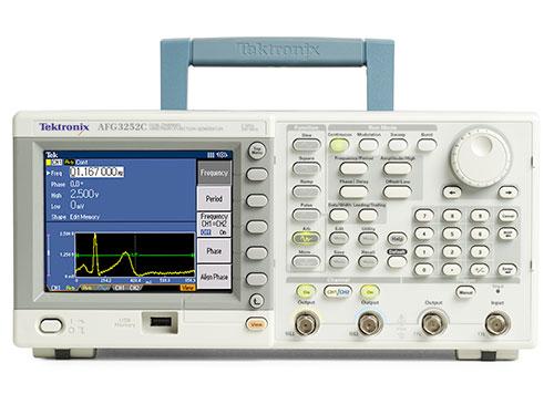
기기명 (Instrument) : Arbitrary Function Generators
제작회사 (Manufacturer) : Tektronix (텍트로닉스)
형식 (Model) : AFG310 / AFG320
세부내용 (Description) :
Features & Benefits
-. Five Functions in One Instrument
- Function Generator
- Arbitrary Waveform Generator
- Burst Generator
- Sweep Generator
- Modulation Source
-. AFG320 Offers Two Independent Channels
-. Load Waveforms Directly from Selected Tektronix Digital Oscilloscopes via the GPIB Interface
-. Windows-based ArbExpress™ Software Package Included for Convenient Creation and Editing of Arbitrary Waveforms
All Functions Including Waveform Creation and Editing Accessible via the Front Panel
-. Optional Rackmount Kit for System Applications
Applications
-. Simulate Waveforms in Design, Test and Manufacturing
-. Computer and Communications
- Serial Data and Clock
- Magnetic Card Readers
- Power Supply Loads
- Noise Injection
-. Automotive
- Engine Control Modules
- Ignition Systems
- Anti-lock Braking
- Safety Restraining Systems
-. Biomedical
- Physiological Responses
- Heart Fibrillation
- EEG and EKG
-. Industrial
- Sensor Simulation
- Actuator Drive Signals
-. Education
- Laboratory Classes
- Graduate Research
AFG300 Series Delivers Five Functions in One Tool
Function Generator
The AFG300 Series is an excellent 16 MHz function generator with built-in arbitrary waveform, burst, sweep, and modulation capabilities. The instruments support standard waveforms including sine, square, triangle, ramp, pulse, DC and noise. Its sweep function includes Linear and Logarithmic (up or down) while operating in the Continuous, Triggered, and Burst modes.
Arbitrary Waveform Generation
With a sample rate of 16 MS/s, 12-Bit vertical resolution and a non-volatile memory that holds four 16,384-point waveforms, the AFG300 Series are powerful tools for simulating complex waveforms. Waveforms can be downloaded directly from selected Tektronix oscilloscopes and arbitrary waveform generators via GPIB, created with the standard ArbExpress™ waveform editing software package, or entered via the front panel.
Specification
Characteristics
Output Channels -
AFG310: 1.
AFG320: 2.
Standard Waveforms - Sine, Square, Triangle, Ramp, Pulse, DC and Noise.
User Waveforms - (Preprogrammed samples)
USR1: Sin (X)/X
USR2: Double Exponential Pulse
USR3: Damped Sine Wave
USR4: NRZ Random Signal
Arbitrary Waveforms -
Waveform Length: 10 to 16384 points.
Vertical Resolution: 12-Bit.
Sample Rate: 16 MS/s.
Nonvolatile Memory: Four 16 k waveforms.
Output Frequency -
Sine, Square: 0.01 Hz to 16 MHz.
Triangle, Ramp, Pulse: 0.01 Hz to 100 kHz.
Noise (Gaussian): Maximum 8 MHz bandwidth.
Arbitrary Waveform:
Repetition Rate: 0.01 Hz to 1.6 MHz.
Resolution: 7 digits.
Accuracy: 50 ppm.
Output Characteristics -
Amplitude (into 50 Ω): 50 mVp-p to 10 Vp-p.
Accuracy: ±(1% of setting + 5 mV) at 1 kHz, no offset.
Flatness (at 1 V amplitude relative to 1 kHz):
<100 kHz: ±1%.
100 kHz to 1 MHz: ±1.5%.
1 MHz to 16 MHz: ±3%.
Offset (into 50 Ω):
505 mVp-p to 10 Vp-p amplitude: peak amplitude + offset is limited to +5 V or -5 V.
50 mVp-p to 500 mVp-p amplitude: -0.75 V to +0.75 V.
Accuracy: ±(1% of setting +5 mV).
Resolution: 5 mV.
Output Impedance: 50 Ω.
Isolation: 42 V peak maximum relative to earth ground.
Phase:
Range: ±360°.
Resolution: 1°.
Sine Wave Spectral Purity -
Harmonic Distortion:
DC to 20 kHz: -65 dBc.
20 kHz to 100 kHz: -60 dBc.
100 kHz to 1 MHz: -45 dBc.
1 MHz to 16 MHz: -35 dBc.
Total Harmonic Distortion:
20 kHz: 0.05% at 1 V amplitude.
Signal Characteristics -
Square:
Rise/Fall Time: ≤20 ns.
Overshoot: <<2%.
Pulse:
Rise/Fall Time: <<100 ns.
Duty Cycle: 1% to 99% of period.
Triangle, Ramp, Pulse, Arbitrary:
Jitter: 2 ns at 100 kHz.
Modulation -
AM:
Source: External only.
Carrier: Up to 16 MHz.
Modulation: Any internal waveform plus Arb.
Frequency: DC to 200 kHz.
Depth:
1 V: 100%.
0 V: 50%.
-1 V: 0%.
2 Vp-p for 100% modulation.
FM:
Source: Internal only.
Modulation: Sine, Square, Triangle, Arb.
Frequency: 0.01 Hz to 10 kHz.
Deviation: 0.01 Hz to 8 MHz.
FSK (frequency shift keying):
Source: Internal only.
Mode: Trigger, Burst.
Frequency range: 0.01 Hz to 16 MHz.
Key rate: 0.01 Hz to 50 kHz.
Number of keys: 2.
Frequency Sweep -
Type: Linear or logarithmic.
Direction: Up or down.
Start/Stop Frequency: 0.01 Hz to 16 MHz.
Time: 1 ms to 100 s.
Mode: Continuous, Trigger, Burst.
Operating Mode -
Continuous: The selected waveform is output continuously.
Triggered: One period of the selected waveform is output each time a trigger occurs.
Trigger source: Manual, external.
Burst: The selected waveform is output with a specified number of cycles each time a trigger occurs.
Carrier Frequency: Up to 1 MHz.
Count: 1 to 60,000 cycles/burst (100 s maximum except sine wave or square wave) or infinite.
Start phase: -360 to +360°.
Trigger source: Manual, external.
Inputs/Outputs -
Front panel:
Main output: Ch 1, Ch 2 (AFG320 only).
External Trigger (Burst) input:
TTL input.
Pulse-width: 1 μs minimum.
10 kΩ input impedance.
Rear panel:
Sync output: TTL level.
External AM modulation:
2 Vp-p = 100% modulation.
10 kΩ input impedance.
GPIB Interface (IEEE-488.2).
Memory -
Type: Non-volatile.
Setup Storage: 20.
Arbitrary Waveform Storage: 4.
Environmental, EMC, Safety
Temperature Range -
Operating: 0 °C to +50 °C.
Nonoperating: -20 °C to +60 °C.
Humidity -
Operating:
At or below +40 °C: 0 to 95%.
+40 °C to +50 °C: 0 to 75%.
Random Vibration -
Operating: 0.31 GRMS from 5 to 500 Hz, 10 minutes.
Nonoperating: 2.46 GRMS from 5 to 500 Hz, 10 minutes.
Shock - Nonoperating: 294 m/s2 (30 G), half-sine, 11 ms duration.
EMC Compliance -
Meets intent of Directive 89/396/EEC for Electromagnetic Compatibility.
Australian AN/NZS 2064.1/2.
Safety - UL1244, CSA231, EN61010-1, IEC61010-1.
Power
Line Voltage - 90 to 132 VAC, 180 to 250 VAC.
Line Frequency -
90 to 250 V: 48 to 63 Hz.
90 to 127 V: 48 to 440 Hz.
Physical Characteristics
|
Dimensions |
mm |
in. |
|
Weight |
kg |
lbs. |
|
Height |
99 |
3.9 |
|
Width |
214 |
8.4 |
|
Depth |
411 |
16.2 |
|
Net: AFG310 |
5.4 |
11.9 |
|
Net: AFG320 |
5.6 |
12.3 |
첨부 (Attach)
파일내용 (The content of file) :
-. Datasheet (데이터시트) :
-. User Manual (사용자 설명서) :
-. Service Manual (서비스 매뉴얼) :
-. Instruction Manual (현장 설치 지침) :
사진 (Picture) :

'사용설명서' 카테고리의 다른 글
| GW Instek / AFG-2225_Arbitrary Function Generator (0) | 2020.07.21 |
|---|---|
| Keysight (Agilent) / E3634A_벤치 전원 공급기 (0) | 2020.07.21 |
| Kenwood / CS-4125A_20MHz 2-Channel Oscilloscope (0) | 2020.07.21 |
| NIDEC-SHIMPO / DT-107A_(LED) Tachometer (0) | 2020.07.21 |
| NIDEC-SHIMPO / DT-207LR_(LED) Tachometer (0) | 2020.07.21 |
기기명 (Instrument) : 임의/함수 발생기 (Arbitrary/Function Generators)
제작회사 (Manufacturer) : Tektronix (텍트로닉스)
형식 (Model) : AFG3000C serise
(AFG3101 , AFG3102 , AFG3251 , AFG3252 , AFG3021B , AFG3022B , AFG3011 , AFG3011C , AFG3021C , AFG3022C , AFG3051C , AFG3052C , AFG3101C , AFG3102C , AFG3251C , AFG3252C)
세부내용 (Description) :
최신 시스템의 다양한 신호를 테스트 하는 것은 복잡하고 어렵게 느껴집니다. 12개의 표준 파형, 임의 파형 기능, 신호 감쇠 옵션을 갖춘 AFG3000C 임의/함수 발생기 시리즈는 단일 측정 장비에서 많이 사용되는 매우 다양한 애플리케이션을 지원합니다. 동급 최고의 성능으로 신호의 정확한 재현을 보장합니다. AFG3000C 임의/함수 발생기 시리즈는 대형 디스플레이가 설치되어 있고 25개의 바로 가기 키가 제공되어 사용하기가 매우 쉽습니다.
개요
특징 |
장점 |
|
듀얼 채널 모델 |
두 개의 신호 발생기 대신 두 개로 정밀하게 동기화되거나 두 개로 완전히 분리된 신호를 사용하는 단일 장비로 대체함으로써 비용과 작업 공간을 절약할 수 있습니다. |
|
최대 1GS/s의 샘플링 속도 |
파형을 세밀한 타이밍 해상도로 생성합니다. |
|
최대 20V |
외부 전력 증폭기를 사용하지 않고 높은 변조 신호를 생성하여 비용과 설치 시간을 절약할 수 있습니다. |
|
25개의 바로 가기 키 |
자주 사용하는 기능 및 매개 변수에 바로 액세스하여 설치 및 평가 테스트 시간을 확연하게 줄일 수 있습니다. |
|
대형 142mm(5.6인치) 컬러 디스플레이 |
모든 관련 설정 및 파형 그래프를 한눈에 볼 수 있어 자신 있게 신호를 확인할 수 있습니다. |
|
약 168mm(6.6인치)의 폭 |
작업 공간을 절약할 수 있습니다. |
|
ArbExpress™ 소프트웨어 |
파형을 쉽게 생성 및 수정할 수 있으며, Tektronix 오실로스코프에서 파형을 원활하게 가져오거나 등식 편집기, 자유 곡선, 포인트 그리기 또는 파형 연산을 통해 파형을 생성할 수 있습니다. |
Unmatched performance, versatility, intuitive operation, and affordability make the AFG3000C Series of Function, Arbitrary Waveform, and Pulse Generators the most useful instruments in the industry.
Key performance specifications
-. 10 MHz, 25 MHz, 50 MHz, 100 MHz, 150 MHz, or 240 MHz sine waveforms
-. 14 bits, 250 MS/s, 1 GS/s, or 2 GS/s arbitrary waveforms
-. Amplitude up to 20 Vp-p into 50 Ω loads
Key features
-. 5.6 in. display for full confidence in settings and waveform shape
-. Multi-language and intuitive operation saves setup time
-. Pulse waveform with variable edge tmes
-. AM, FM, PM, FSK, PWM
-. Sweep and burst
-. Dual-channel models save cost and bench space
-. USB connector on front panel for waveform storage on memory device
-. USB, GPIB, and LAN
-. LabVIEW and LabWindows/IVI-C drivers
Applications
-. Electronic test and design
-. Sensor simulation
-. Functional test
-. Education and training
Superior performance and versatility
Users can choose from 12 different standard waveforms. Arbitrary waveforms can be generated up to 128 K in length at high sampling rates. On pulse waveforms, leading and trailing edge time can be set independently. External signals can be connected and added to the output signal. Dual-channel models can generate two identical or completely different signals. All instruments feature a highly stable time base with only ±1 ppm drift per year.
Intuitive user interface shows more information at a single glance
Color TFT LCD screen on all models shows all relevant waveform parameters and graphical wave shape at a single glance. This gives full confidence in the signal settings and lets you focus on the task at hand. Shortcut keys provide direct access to frequently used functions and parameters. Others can be selected conveniently through clearly structured menus. This reduces the time needed for learning and relearning how to use the instrument. Look and feel are identical to the world's most popular TDS3000 Oscilloscopes.
ArbExpress™ software included for creating waveforms with ease
With this PC software waveforms can be seamlessly imported from any Tektronix oscilloscope, or defined by standard functions, equation editor, and waveform math.
Specifications 1
All specifications are guaranteed unless noted otherwise. All specifications apply to all models unless noted otherwise.
1 The given typical values are not warranted. But 80% or more manufactured units will perform to the level indicated at room temperature (approximately 25 °C).
Model overview
Sine waves
Frequency range
|
AFG3011C |
AFG3021C, AFG3022C |
AFG3051C, AFG3052C |
|
1 µHz to 10 MHz |
1 µHz to 25 MHz |
1 µHz to 50 MHz |
Sine wave in Burst Mode
|
1 µHz to 5 MHz |
1 µHz to 12.5 MHz |
1 µHz to 25 MHz |
Effective maximum frequency out
|
10 MHz |
25 MHz |
50 MHz |
Amplitude flatness (1 Vp-p)
|
<5 MHz: ±0.15 dB |
<5 MHz: ±0.15 dB |
<5 MHz: ±0.15 dB |
Amplitude flatness (1 Vp-p), typical
|
<5 MHz: ±0.11 dB |
<5 MHz: ±0.06 dB |
<5 MHz: ±0.06 dB |
Harmonic distortion (1 Vp-p)
|
10 Hz to 20 kHz: < -60 dBc |
10 Hz to 20 kHz: < -70 dBc |
10 Hz to 20 kHz: < -70 dBc |
Harmonic distortion (1 Vp-p), typical
|
10 Hz to 20 kHz: < -73 dBc |
10 Hz to 20 kHz: < -77 dBc |
10 Hz to 20 kHz: < -75 dBc |
THD
|
≤0.2% (<0.15%, typical), 10 Hz to 20 kHz, 1 Vp-p |
Spurious(1 Vp-p)
|
10 Hz to 1 MHz: < -60 dBc |
10 Hz to 1 MHz: < -60 dBc |
10 Hz to 1 MHz: < -60 dBc |
Spurious(1 Vp-p), typical
|
10 Hz to 1 MHz: < -61 dBc |
10 Hz to 1 MHz: < -71 dBc |
10 Hz to 1 MHz: < -71 dBc |
Phase noise, typical
|
< -110 dBc/Hz at 10 MHz, 10 kHz offset, 1 Vp-p |
< -110 dBc/Hz at 20 MHz, 10 kHz offset, 1 Vp-p |
Residual clock noise
|
-63 dBm |
-63 dBm |
-63 dBm |
Square waves
Frequency range
|
AFG3011C |
AFG3021C, AFG3022C |
AFG3051C, AFG3052C |
|
1 µHz to 5 MHz |
1 µHz to 25 MHz |
1 µHz to 40 MHz |
Rise/fall time
|
≤50 ns |
≤9 ns |
≤7 ns |
Jitter (RMS)
|
500 ps |
500 ps |
300 ps |
Jitter (RMS), typical
|
<210 ps |
<60 ps |
<60 ps |
Ramp waves
Frequency range
|
AFG3011C |
AFG3021C, AFG3022C |
AFG3051C, AFG3052C |
|
1 µHz to 100 kHz |
1 µHz to 500 kHz |
1 µHz to 800 kHz |
Linearity, typical
|
≤0.2% of peak output |
≤0.1% of peak output |
≤0.1% of peak output |
Symmetry
|
0% to 100.0% |
Pulse waves
Frequency range
|
AFG3011C |
AFG3021C, AFG3022C |
AFG3051C, AFG3052C |
|
1 mHz to 5 MHz |
1 mHz to 25 MHz |
1 mHz to 40 MHz |
Pulse width
|
80.00 ns to 999.99 s |
16 ns to 999.99 s |
12 ns to 999.99 s |
Resolution
|
10 ps or 5 digits |
Pulse duty
|
0.001% to 99.999% (Limitations of pulse width apply) |
Edge transition time
|
50 ns to 625 s |
9 ns to 625 s |
7 ns to 625 s |
Resolution
|
10 ps or 4 digits |
Lead delay: range
|
(Continuous Mode): 0 ps to Period |
Lead delay: resolution
|
10 ps or 8 digits |
Overshoot, typical
|
<5% |
Jitter (RMS)
|
500 ps |
500 ps |
300 ps |
Jitter (RMS), typical
|
<210 ps |
<60 ps |
<60 ps |
Other waveforms
Frequency range
|
AFG3011C |
AFG3021C, AFG3022C |
AFG3051C, AFG3052C |
|
1 µHz to 100 kHz |
1 µHz to 500 kHz |
1 µHz to 800 kHz |
Noise bandwidth (-3 dB)
|
10 MHz |
25 MHz |
50 MHz |
Noise type:
|
White Gaussian |
Internal noise add
|
When activated, output signal amplitude is reduced to 50% |
Level
|
0.0% to 50% of amplitude (Vp-p) setting |
Resolution
|
1% |
DC (into 50 Ω)
|
-10 V to +10 V |
-5 V to +5 V |
-5 V to +5 V |
Arbitrary waveforms
Frequency range
|
AFG3011C |
AFG3021C, AFG3022C |
AFG3051C, AFG3052C |
|
1 mHz to 5 MHz |
1 mHz to 12.5 MHz |
1 mHz to 25 MHz |
Arbitrary waveforms in Burst Mode
|
1 mHz to 2.5 MHz |
1 mHz to 6.25 MHz |
1 mHz to 12.5 MHz |
Effective analog bandwidth (-3 dB)
|
8 MHz |
70 MHz |
Nonvolatile memory
|
4 waveforms |
Memory: Sample rate (1K=1024 points)
|
2 to 128 K: 250 MS/s |
2 to 128 K: 250 MS/s |
2 to 16 K: 1 GS/s |
Vertical resolution
|
14 bits |
Rise/fall time
|
≤80 ns |
≤14 ns |
≤10 ns |
Jitter (RMS)
|
4 ns |
4 ns |
1 ns at 1 GS/s 4 ns at 250 MS/s |
Amplitude
Range, 50 Ω Load
|
AFG3011C |
AFG3021C, AFG3022C |
AFG3051C, AFG3052C |
|
20 mVp-p to 20 Vp-p |
10 mVp-p to 10 Vp-p |
10 mVp-p to 10 Vp-p |
Range (open circuit or High Z)
|
40 mVp-p to 40 Vp-p |
20 mVp-p to 20 Vp-p |
20 mVp-p to 20 Vp-p |
Accuracy
|
±(2% of setting +2 mV) |
±(1% of setting +1 mV) (1 kHz sine wave, 0 V offset, >10 mVp-p amplitude) |
Accuracy, typical
|
±(1% of setting +5 mV) |
±(0.5% of setting +0.5 mV) (1 kHz sine wave, 0 V offset, >10 mVp-p amplitude) |
Resolution
|
0.1 mVp-p, 0.1 mVRMS, 1 mV, 0.1 dBm or 4 digits |
Units
|
Vp-p, VRMS, dBm (sine wave only) and Volt (high/low setting) |
Output impedance
|
50 Ω |
Load impedance setting
|
Selectable: 50 Ω, 1 Ω to 10.0 kΩ, High Z (Adjusts displayed amplitude according to selected load impedance) |
Isolation
|
42 Vpk maximum to earth |
Short-circuit protection
|
Signal outputs are robust against permanent shorts against floating ground |
External voltage protection
|
To protect signal outputs against external voltages use fuse adapter 013-0345-xx |
DC offset
Range (50 Ω load)
|
AFG3011C |
AFG3021C, AFG3022C |
AFG3051C, AFG3052C |
|
±(10 Vpk - Amplitudep-p ÷ 2) |
±(5 Vpk - Amplitudep-p ÷ 2) |
±(5 Vpk - Amplitudep-p ÷ 2) |
Range (open circuit or High Z)
|
±(20 Vpk - Amplitudep-p ÷ 2) |
±(10 Vpk - Amplitudep-p ÷ 2) |
±(10 Vpk - Amplitudep-p ÷ 2) |
Accuracy
|
±(2% of |setting| + 10 mV + 1% of amplitude (Vp-p )) |
±(1% of |setting| + 5 mV + 0.5% of amplitude (Vp-p )) |
Resolution
|
1 mV |
General characteristics (AFG3100 & AFG3200 series)
Sine waves
Frequency range
|
AFG3101C, AFG3102C |
AFG3151C, AFG3152C |
AFG3251C, AFG3252C |
|
1 µHz to 100 MHz |
1 µHz to 150 MHz |
1 µHz to 240 MHz |
Sine wave in Burst Mode
|
1 µHz to 50 MHz |
1 µHz to 75 MHz |
1 µHz to 120 MHz |
Effective maximum frequency out
|
100 MHz |
150 MHz |
240 MHz |
Amplitude flatness (1 Vp-p)
|
<5 MHz: ±0.15 dB |
<5 MHz: ±0.15 dB |
<5 MHz: ±0.15 dB |
Amplitude flatness (1 Vp-p), typical
|
<5 MHz: ±0.03 dB |
>5 MHz: ±0.04 dB |
<5 MHz: ±0.03 dB |
Harmonic distortion (1 Vp-p)
|
10 Hz to 1 MHz: < -60 dBc |
<5 MHz: ±0.15 dB |
10 Hz to 1 MHz: < -60 dBc |
Harmonic distortion (1 Vp-p), typical
|
10 Hz to 1 MHz: < -72 dBc |
10 Hz to 1 MHz: < -72 dBc |
10 Hz to 1 MHz: < -67 dBc |
THD
|
≤0.2% (<0.15%, typical), 10 Hz to 20 kHz, 1 Vp-p |
Spurious(1 Vp-p)
|
10 Hz to 1 MHz: < -60 dBc |
10 Hz to 1 MHz: < -60 dBc |
10 Hz to 1 MHz: < -50 dBc |
Spurious(1 Vp-p), typical
|
10 Hz to 1 MHz: < -71 dBc |
10 Hz to 1 MHz: < -70 dBc |
10 Hz to 1 MHz: < -63 dBc |
Phase noise, typical
|
< -110 dBc/Hz at 20 MHz, 10 kHz offset, 1 Vp-p |
Residual clock noise
|
-57 dBm |
Square waves
Frequency range
|
AFG3101C, AFG3102C |
AFG3151C, AFG3152C |
AFG3251C, AFG3252C |
|
1 µHz to 50 MHz |
1 µHz to 100 MHz |
1 µHz to 120 MHz |
Rise/fall time
|
≤5 ns |
≤3.5 ns |
≤2.5 ns |
Jitter (RMS)
|
200 ps |
150 ps |
100 ps |
Jitter (RMS), typical
|
<35 ps |
<35 ps |
<35 ps |
Ramp waves
Frequency range
|
AFG3101C, AFG3102C |
AFG3151C, AFG3152C |
AFG3251C, AFG3252C |
|
1 µHz to 1 MHz |
1 µHz to 1.5 MHz |
1 µHz to 2.4 MHz |
Linearity, typical
|
≤0.15% of peak output |
≤0.15% of peak output |
≤0.2% of peak output |
Symmetry
|
0% to 100.0% |
Pulse waves
Frequency range
|
AFG3101C, AFG3102C |
AFG3151C, AFG3152C |
AFG3251C, AFG3252C |
|
1 mHz to 50 MHz |
1 mHz to 100 MHz |
1 mHz to 120 MHz |
Pulse width
|
8.00 ns to 999.99 s |
5.00 ns to 999.99 s |
4.00 ns to 999.99 s |
Resolution
|
10 ps or 5 digits |
Pulse duty
|
0.001% to 99.999% (Limitations of pulse width apply) |
Edge transition time
|
5 ns to 625 s |
3 ns to 625 s |
2.5 ns to 625 s |
Resolution
|
10 ps or 4 digits |
Lead delay: range
|
(Continuous Mode): 0 ps to Period |
Lead delay: resolution
|
10 ps or 8 digits |
Overshoot, typical
|
<5% |
Jitter (RMS)
|
200 ps |
150 ps |
100 ps |
Jitter (RMS), typical
|
<35 ps |
<25 ps |
<35 ps |
Other waveforms
Frequency range
|
AFG3101C, AFG3102C |
AFG3151C, AFG3152C |
AFG3251C, AFG3252C |
|
1 µHz to 1 MHz |
1 µHz to 1.5 MHz |
1 µHz to 2.4 MHz |
Noise bandwidth (-3 dB)
|
100 MHz |
180 MHz |
240 MHz |
Noise type:
|
White Gaussian |
Internal noise add
|
When activated, output signal amplitude is reduced to 50% |
Level
|
0.0% to 50% of amplitude (Vp-p) setting |
Resolution
|
1% |
DC (into 50 Ω)
|
-5 V to +5 V |
-5 V to +5 V |
-2.5 V to +2.5 V |
Arbitrary waveforms
Frequency range
|
AFG3101C, AFG3102C |
AFG3151C, AFG3152C |
AFG3251C, AFG3252C |
|
1 mHz to 50 MHz |
1 mHz to 100 MHz |
1 mHz to 120 MHz |
Arbitrary waveforms in Burst Mode
|
1 mHz to 25 MHz |
1 mHz to 50 MHz |
1 mHz to 60 MHz |
Effective analog bandwidth (-3 dB)
|
100 MHz |
180 MHz |
225 MHz |
Nonvolatile memory
|
4 waveforms |
Memory: Sample rate (1K=1024 points)
|
2 to 16 K: 1 GS/s |
2 to 16 K: 1 GS/s |
2 to 16 K: 2 GS/s |
Vertical resolution
|
14 bits |
Rise/fall time
|
≤8 ns |
5 ns |
≤3 ns |
Jitter (RMS)
|
1 ns at 1 GS/s 4 ns at 250 MS/s |
750 ps at 1 GS/s 4 ns at 250 MS/s |
500 ps at 2 GS/s 4 ns at 250 MS/s |
Amplitude
Range, 50 Ω Load
|
AFG3101C, AFG3102C |
AFG3151C, AFG3152C |
AFG3251C, AFG3252C |
|
20 mVp-p to 10 Vp-p |
≤100 MHz: 20 mVp-p to 10 Vp-p >100 MHz: 20 mVp-p to 8 Vp-p |
≤200 MHz: 50 mVp-p to 5 Vp-p >200 MHz: 50 mVp-p to 4 Vp-p |
Range (open circuit or High Z)
|
40 mVp-p to 20 Vp-p |
≤100 MHz: 40 mVp-p to 20 Vp-p>100 MHz: 40 mVp-p to 16 Vp-p |
≤200 MHz: 100 mVp-p to 10 Vp-p>200 MHz: 100 mVp-p to 8 Vp-p |
Accuracy
|
±(1% of setting +1 mV) (1 kHz sine wave, 0 V offset, >10 mVp-p amplitude) |
Accuracy, typical
|
±(0.5% of setting +0.5 mV) (1 kHz sine wave, 0 V offset, >10 mVp-p amplitude) |
Resolution
|
0.1 mVp-p, 0.1 mVRMS, 1 mV, 0.1 dBm or 4 digits |
Units
|
Vp-p, VRMS, dBm (sine wave only) and Volt (high/low setting) |
Output impedance
|
50 Ω |
Load impedance setting
|
Selectable: 50 Ω, 1 Ω to 10.0 kΩ, High Z (Adjusts displayed amplitude according to selected load impedance) |
Isolation
|
42 Vpk maximum to earth |
Short-circuit protection
|
Signal outputs are robust against permanent shorts against floating ground |
External voltage protection
|
To protect signal outputs against external voltages use fuse adapter 013-0345-xx |
DC offset
Range (50 Ω load)
|
AFG3101C, AFG3102C |
AFG3151C, AFG3152C |
AFG3251C, AFG3252C |
|
±5 Vpk DC |
±5 Vpk DC |
±2.5 Vpk DC |
Range (open circuit or High Z)
|
±10 Vpk DC |
±10 Vpk DC |
±5 Vpk DC |
Accuracy
|
±(1% of |setting| + 5 mV + 0.5% of amplitude (Vp-p )) |
Resolution
|
1 mV |
System characteristics
Frequency resolution
1 μHz or 12 digits
Internal frequency reference
Stability
All except ARB: ±1 ppm, 0 °C to 50 °C
ARB: ±1 ppm ± 1 µHz, 0 °C to 50 °C
Aging
±1 ppm per year
Phase (except DC, noise, pulse)
Range
-180° to +180°
Resolution
0.01° (sine), 0.1° (other waveforms)
Internal noise add
When activated, output signal amplitude is reduced to 50%
Level
0.0% to 50% of amplitude (Vp-p) setting
Resolution
1%
Main output
50 Ω
Remote programming: configuration times, max, typical
GPIB, LAN 10BASE-T / 100BASE-TX, USB 1.1
Compatible with SCPI-1999.0 and IEEE 488-2 standards
Function change
|
USB |
LAN |
GPIB |
|
81 ms |
81 ms |
81 ms |
Frequency change (except Pulse)
|
2.5 ms |
6 ms |
3.2 ms |
Frequency change (Pulse)
|
40 ms |
37 ms |
32 ms |
Amplitude change
|
90 ms |
97 ms |
90 ms |
Select user ARB (4k points from USB Memory)
|
48 ms |
50 ms |
49 ms |
Select user ARB (128k points from USB Memory)
|
260 ms |
266 ms |
240 ms |
Remote programming: data download time for 4000 point waveform data, typical
|
USB |
LAN |
GPIB |
|
47 ms |
78 ms |
320 ms |
Power source
100-240 V, 47-63 Hz, or 115 V, 360-440 Hz
Power consumption
Less than 120 W
Warm up time, typical
20 minutes
Power on self-diagnosis, typical
<10 s
Acoustic noise, typical
<50 dBA
Display
5.6 in. Color TFT LCD
User interface and Help languages
English, French, German, Japanese, Korean, Portuguese, Simplified and Traditional Chinese, Russian (user selectable)
Modulation characteristics
AM, FM, PM
Carrier waveforms
All except Pulse, Noise, and DC
Source
Internal/external
Internal modulating waveform
Sine, square, ramp, noise, ARB
(AM: maximum waveform length 4,096; FM/PM: maximum waveform length 2,048)
Internal modulating frequency
2 mHz to 50.00 kHz
AM modulation depth
0.0% to +120.0%
Min FM peak deviation
DC
Max FM peak deviation
See following table, Modulation: Max FM Peak Deviation
PM phase deviation
-360.0° to +360.0°
Pulse width modulation
Carrier waveform
Pulse
Source
Internal/external
Internal modulating waveform
Sine, square, ramp, noise, ARB
(maximum waveform length 2,048)
Internal modulating frequency
2 mHz to 50.00 kHz
Deviation
0% to 50.0% of pulse period
Max FM peak deviation
Sine
|
AFG3011C |
AFG3021C, AFG3022C |
AFG3051C, AFG3052C |
AFG3101C, AFG3102C |
AFG3151C, AFG3152C |
AFG3251C, AFG3252C |
|
5 MHz |
12.5 MHz |
25 MHz |
50 MHz |
75 MHz |
120 MHz |
Square
|
2.5 MHz |
12.5 MHz |
20 MHz |
25 MHz |
50 MHz |
60 MHz |
ARB
|
2.5 MHz |
6.25 MHz |
12.5 MHz |
25 MHz |
50 MHz |
60 MHz |
Others
|
50 kHz |
250 kHz |
400 kHz |
500 kHz |
750 kHz |
1.2 MHz |
Frequency shift keying
Carrier waveforms
All, except Pulse, Noise, and DC
Source
Internal/external
Internal modulating frequency
2 mHz to 1,000 MHz
Number of keys
2
Sweep
Waveforms
All, except Pulse, Noise, and DC
Type
Linear, logarithmic
Sweep time
1 ms to 300 s
Hold/return time
0 ms to 300 s
Max total sweep time
300 s
Resolution
1 ms or 4 digits
Total sweep time accuracy, typical
≤0.4%
Min start/stop frequency
All except ARB: 1 µHz
ARB: 1 mHz
Max start/stop frequency
See chart, below
Sweep: max start/stop frequency
Sine
|
AFG3011C |
AFG3021C, AFG3022C |
AFG3051C, AFG3052C |
AFG3101C, AFG3102C |
AFG3151C, AFG3152C |
AFG3251C, AFG3252C |
|
10 MHz |
25 MHz |
50 MHz |
100 MHz |
150 MHz |
240 MHz |
Square
|
5 MHz |
25 MHz |
40 MHz |
50 MHz |
100 MHz |
120 MHz |
ARB
|
5 MHz |
12.5 MHz |
25 MHz |
50 MHz |
100 MHz |
120 MHz |
Others
|
100 kHz |
500 kHz |
800 kHz |
1 MHz |
1.5 MHz |
2.4 MHz |
Burst
Waveforms
All, except Noise and DC
Type
Triggered, gated (1 to 1,000,000 cycles or Infinite)
Internal trigger rate
1 μs to 500.0 s
Gate and trigger sources
Internal, external, remote interface
Auxiliary input characteristics
Modulation inputs
Channel 1, Channel 2
Input range
All except FSK: ±1 V
FSK: 3.3 V logic level
Impedance
10 kΩ
Frequency range
DC to 25 kHz (122 kS/s)
External Triggered/Gated Burst input
Level
TTL compatible
Impedance
10 kΩ
Pulse width
100 ns minimum
Slope
Positive/negative, selectable
Trigger delay
0.0 ns to 85.000 s
Trigger delay resolution
100 ps or 5 digits
Jitter (RMS), typical
Burst: <500 ps (trigger input to signal output)
10 MHz reference input
Impedance
1 kΩ, AC coupled
Required input voltage swing
100 mVp-p to 5 Vp-p
Lock range
10 MHz ±35 kHz
External channel 1 add input
AFG3101C, AFG3102C, AFG3151C, AFG3152C, AFG3251C, AFG3252C only
Impedance
50 Ω
Input range
-1 V to +1 V (DC + peak AC)
Bandwidth
DC to 10 MHz (-3 dB) at 1 Vp-p
Auxiliary output characteristics
Trigger output (Channel 1)
Level
Positive TTL level pulse into 1 kΩ
Impedance
50 Ω
Jitter (RMS), typical
AFG3011C/21C/22C: 500 ps
AFG3051C/52C: 300 ps
AFG3101C/02C: 200 ps
AFG3151C/52C: 150 ps
AFG3251C/52C: 100 ps
Max frequency
4.9 MHz
(4.9 MHz to 50 MHz: A fraction of the frequency is output;
>50 MHz: no signal is output)
Clock reference out (10 MHz)
AFG3011C, AFG3101C, AFG3102C, AFG3151C, AFG3152C, AFG3251C, AFG3252C only
Impedance
50 Ω, AC coupled
Amplitude
1.2 Vp-p into 50 Ω load
Physical characteristics
Benchtop configuration
Dimensions
Height
156 mm (6.2 in.)
Width
329.6 mm (13.0 in.)
Depth
168.0 mm (6.6 in.)
Weight
Net
4.5 kg (9.9 lb.)
Shipping
5.9 kg (12.9 lb.)
EMC environmental and safety characteristics
Temperature
Operating
0 °C to +50 °C
Non-operating
-30 °C to +70 °C
Humidity
Operating
≤ +40 °C: ≤80%
> +40 °C to 50 °C: ≤60%
Altitude
Up to 3,000 m (10,000 ft.)
EMC compliance
European Union
EU Council Directive 2004/108/EC
Safety
UL 61010-1:2004
CAN/CSA C22.2 No. 61010-1:2004
IEC 61010-1:2001
첨부 (Attach)
파일내용 (The content of file) :
-. Datasheet (데이터시트) :
-. 빠른 시작 사용 설명서 (Quick Manual) :
사진 (Picture) :
'사용설명서' 카테고리의 다른 글
| Cropico (Seaward Group) 005, 006 & 008 series_Decade Resistance Boxes (0) | 2020.07.21 |
|---|---|
| Yokogwa / 700925_차동프로브 (DIFFERENTIAL PROBE) 15MHz/1000V (0) | 2020.07.21 |
| FLUKE / 120B Series_산업용 ScopeMeter™ 휴대용 오실로스코프 (0) | 2020.07.21 |
| KEITHLEY / 428_Programmable Current Amplifier (0) | 2020.07.21 |
| Keysight (Agilent) / MSO6054A_혼합 신호 오실로스코프: 500 MHz, 아날로그 4채널 + 디지털 16채널 (2) | 2020.07.20 |
기기명 (Instrument) : Waveform Vector Monitor
제작회사 (Manufacturer) : Tektronix
형식 (Model) : 1740A, 1750A, 1760 Series
1740A : NTSC Waveform/Vector Monitor.
1741A : PAL Waveform/Vector Monitor.
1745A : NTSC/PAL Waveform/Vector Monitor.
1750A : NTSC Waveform/Vector/SCH Monitor.
1751A : PAL Waveform/Vector/SCH Monitor.
1755A : NTSC/PAL Waveform/Vector/SCH Monitor.
1760A : NTSC/Component Waveform/Vector Monitor.
1761A : PAL/Component Waveform/Vector Monitor.
1765 : NTSC/PAL/Component Waveform/Vector Monitor.
세부내용 (Description) :
Features & Benefits
- Composite or Component Waveform Monitoring
- Composite Vector Display
- Picture Display
- Stereo Audio Display
- Time Code Phasing and Amplitude
- SCH and Color Framing Display
- Component Vector, Lightning, Diamond, and Bowtie
Applications
- Analog Baseband Video Monitoring for Broadcast and Postproduction Applications
The 1740A/1750A/1760 Series make up a family of analog video waveform/vector monitors with progressive features in support of today's demanding television environment.
Each model in the series provides improved video performance and ease of operation and incorporates application-specific features. The family includes the 1740A Series composite analog waveform/vector monitors, the 1750A Series, which adds SCH and color frame verification capabilities, and the 1760 Series for mixed-format component/composite applications. (While the 1740A and 1750A do provide basic component waveform monitoring capabilities with parade and overlay displays, only the 1760 provides full component monitoring capabilities.)
Each series includes models for NTSC, PAL, or dual-standard NTSC/PAL operation. For NTSC models, the last digit of the model number is '0' (1740A, 1750A, or 1760); '1' for PAL (1741A, 1751A, or 1761); and '5' for dual-standard NTSC/PAL (1745A, 1755A, or 1765).
The family features a common, straightforward operator interface, allowing the operator to take immediate advantage of the instrument's extensive feature set. Each operating mode provides a full set of operating controls, clearly labeled and within easy reach. Key controls are always available, with bezel buttons and knobs identified by intuitive on-screen labels.
Selection Guide
|
Product Applications |
1740A Series |
1750A Series |
1760 Series |
|
Composite or Component Waveform Monitoring |
X |
X |
X |
|
Composite Vector Display |
X |
X |
X |
|
Picture Display |
X |
X |
X |
|
Stereo Audio Display |
X |
X |
X |
|
Time Code Phasing and Amplitude |
X |
X |
X |
|
SCH and Color Framing Display |
|
X |
Opt. SC |
|
Component Vector, Lightning, Diamond, and Bowtie |
|
|
X |
All family members provide the following standard features:
Eight Video Inputs eliminate the requirement for external input selectors, reducing total system cost in many applications. Since all eight inputs are connected directly to the instrument, signals may be paraded, overlaid, or displayed in comparison modes not normally available with a simple external switcher.
Waveform monitoring is analog for maximum waveform fidelity. There is no digital processing of the displayed signal. The selected input may be displayed in one- or two-line or one- or two-field sweeps on a continuous basis or identified lines of any field may be selected and displayed. Multiple inputs may be displayed at the same time or multiple filters may be applied to one input for signal analysis. Time and voltage cursors may be activated and positioned for reference or measurement.
Composite Vectorscope functions demodulate and display the color components of the NTSC or PAL signal. A microprocessor-controlled phase shifter provides accurate vector positioning and eliminates readjustment when switching between internal and external reference modes. Phase and amplitude cursors with on-screen readout allow system setup to reproduce specific chroma values and specific colors when luminance is similarly set using the waveform-display voltage cursors.
A Picture Monitor mode is provided for easy signal identification. This is particularly useful when the instrument is used to monitor many sources, as in a production suite or outside production vehicle. In waveform or vector line select mode, a line bright-up marker in the picture display identifies the selected line.
Stereo Audio Amplitude and Phase are monitored using a calibrated L/R Lissajous display. The operator can quickly see that the program audio will be properly reproduced on both monaural and stereo receivers. Correct phasing between two audio channels is quickly verified by the direction of the display; signal level (left + right) is confirmed relative to the CRT graticule; and stereo separation (left - right) is displayed in quadrature to the level display.
Audio frequency -3 dB bandwidth is 200 kHz. Phase match between the left and right channels is better than 1 degree at 20 kHz. Input is high-impedance bridging, either balanced or unbalanced, to allow signal monitoring of existing audio circuits.
This display of stereo audio is intuitive and easy to use and has gained wide acceptance in new-generation Tektronix vectorscopes.
Longitudinal Time Code is monitored in a frame rate display to allow observation of amplitude, synchronization, and phase with respect to reference vertical. Synchronization is confirmed by the stationary display and time code phase is easily determined by horizontal position of the time code sync word on the CRT.
These monitors provide multiple display modes, allowing simultaneous observation of the many important parameters that make up a television signal. For example, vector, waveform, and audio may be displayed together for an indication of signal quality without operator intervention.
In the 1750A, or 1760 with the SCH option, Subcarrier/Horizontal Phase and Color Framing are displayed graphically in the patented Tektronix polar SCH display. Sync jitter over the field is displayed as a moving sync vector dot or displayed as a timing error at a vertical rate to identify the relationship over the field time. Correct color framing is quickly verified by the position of the single sync vector dot relative to the color subcarrier vector when the monitor is externally referenced.
The SCH phase of the reference signal is separately sensed to allow reliable SCH and color framing comparison. Using this method of determining relative SCH phase and color framing eliminates the requirement for a precise horizontal timing match between the reference and measured signals and an external color-field identification input is not required.
User Interface
Characteristic of current-generation Tektronix instruments, an intuitive operator interface allows full instrument utilization with minimal reference to the provided user and maintenance manuals. Operating modes, any of eight video inputs, and key control knobs and buttons are always available for direct access from the front panel.
To keep operation easy and straightforward, the 1740A, 1750A, and 1760 family "learns" the user's preferences for waveform, vector, and picture modes (and SCH in the 1750A and 1760 with the SCH option). Returning to one of these modes restores the previous configuration. Changes to a mode configuration are easily made using front-panel buttons, supplemented by screen-labeled buttons and knobs. Knob operations such as position, gain, phase, etc., are stored as well.
The 1740A/1750A/1760 family is easily configured for special monitoring applications, which may be stored in user presets for easy recall. For example, a program line or off-air VITS may be set up as preset number 3. Preset number 3 could be named and later recalled to display line 19 of the selected input in 2H sweep, with voltage cursors marking proper signal levels. Other presets could be used to immediately access and display signals from other points in the system. Different operators could quickly return to preferred monitoring setups after specialized signal checks.
With eight loopthrough video inputs, the 1740A/1750A/1760 family is a versatile central point system monitor. This capability is particularly useful in the production studio, where several machines, cameras, and composite input/output feeds are in use.
As a machine monitor, the instrument may be operated from a central control panel, with waveform, vector (SCH and color framing with the 1750A Series and 1760 Series with SCH), audio, time code, and servo signals easily observed.
High-performance Design
The control system, based on Motorola's rugged MC68332 32 bit microprocessor with internal co-processing, facilitates instrument control and timing functions. Flash EPROMs simplify updating the instrument to the latest firmware configuration.
The 1740A/1750A/1760 family is based on completely new, high-performance analog video system electronics. Application Specific Integrated Circuits (ASICs), developed by Tektronix specifically to maintain signal fidelity in a television test instrument, handle internal signal routing and amplification. Video performance is tightly controlled providing confidence that the signal display accurately represents the signal under test.
As an example of this new video performance level, the series permits observation of the video signal at up to x10 vertical and x25 horizontal magnification. Any part of the signal may be positioned on-screen in any magnification. Overscan performance at any gain setting is virtually distortion-free.
DC Offset (position match) between two or more displayed channels is within 1 IRE or 7 mV. Loopthrough return loss is better than 40 dB to 10 MHz.
Operational Flexibility
Eight loopthrough video inputs may be connected to the rear panel of the 1740A/1750A/1760 Series, eliminating the need for a dedicated routing switcher bus in many applications. Any of these inputs may be selected singly or in combination from the front panel or through the RS-232 interface. Input selection may also be included in preset configurations recalled using a remote control connector.
A separate external input may be selected to synchronize the display, allowing relative SCH and color framing comparison between two input signals or with the house reference. Because a separate SCH evaluation is done on the reference signal, SCH and color framing displays are accurate over a wide input range.
Signal standards can be automatically selected, NTSC 525/60 or PAL 625/50, in dual-standard 1745A/1755A/1765 models. A CRT graticule suitable for both standards is provided. A microprocessor-controlled phase shifter may be activated to rotate the vector display to the correct position on the display. Once set for each standard, the instrument displays the correct vector rotation when the video standard is changed.
A new universal input power supply is a part of these monitors. AC mains in the range of 90 to 250 V, 50 or 60 Hz, are accommodated automatically. This new power supply will also operate from a nonsinusoidial supply, allowing battery operation using an external, high-efficiency switching inverter. A snap-lock power cord appropriate to the country of use is supplied with each instrument.
첨부 (Attach)
파일내용 (The content of file) : Data Sheet
사진 (Picture) :

'계측기정보' 카테고리의 다른 글
| Shibasoku / TG39A series_Multi Test Signal Generator (0) | 2019.09.03 |
|---|---|
| Autonics / ATM series_초소형 아날로그 타이머 (카탈로그_Catalog) (0) | 2019.08.01 |
| Agilent / 3000 series_Oscilloscope (Data Sheet) (0) | 2019.05.08 |
| TES / 1319A_Thermometer (0) | 2019.05.07 |
| OWON / XDS series_디지털 오실로스코프 (Datasheet) (0) | 2019.05.07 |
기기명 (Instrument) : 디지털 스토리지 오실로스코프 (Digital Storage Oscilloscope)
제작회사 (Manufacturer) : Tektronix
형식 (Model) : TBS2000 series ( TBS2072 / TBS2102 / TBS2074 / TBS2104 )
세부내용 (Description) :
Digital Storage Oscilloscope
This TBS2000 series oscilloscope user manual explains how to operate the oscilloscope and includes installation procedures. It also provides information about features, functions, and applications.
With a 9-inch WVGA display, 20 million point record length and 1 GS/s sample rate, TBS2000 Series Oscilloscopes capture and display significantly more signal to help you evaluate designs faster.
Easily and confidently analyze your signals with new on-waveform cursor readouts and 32 automated measurements, each with informative tips to help you quickly choose the right one. The TekVPI® probe interface works with traditional BNC connections, but also enables wide application coverage with the latest active voltage probes and current probes.
Key performance specifications
-. 2 and 4 analog channel models
-. 100 and 70 MHz bandwidth models
-. Up to 1 GS/s sampling rate
-. 20 M record length on all channels
-. 5 year warranty
Key features
-. 9-inch WVGA color display
-. 15 horizontal grids show 50% more signal
-. TekVPI probe interface supports active, differential, and current probes with automatic scaling and units
-. 32 automated measurements, and FFT function for thorough waveform analysis
-. HelpEverywhere provides helpful on-screen tips
-. Built-in Scope Intro handbook provides operating instructions and oscilloscope fundamentals
-. 2-channel models are highly-portable at 2.62 kg (5.8 lbs)
Connectivity
-. USB 2.0 host port on the front panel for quick and easy data storage
-. Wi-Fi interface provides wireless communications capability 1 support
-. USB 2.0 device port on rear panel for easy connection to a PC
-. LXI compliant 10/100BASE-T Ethernet port for remote control over LAN
-. 1A Wi-Fi adapter is available in some countries from Tektronix distributors as an accessory, model TEK-USB-WIFI. See Ordering Information for details.
Education
-. Courseware function presents lab exercise guidance on the display
-. Fully compatible with TekSmartLab lab management software for education
첨부 (Attach)
파일내용 (The content of file) : User Manual
사진 (Picture) :

'사용설명서' 카테고리의 다른 글
기기명 (Instrument) : 디지털 스토리지 오실로스코프 (Digital Storage Oscilloscope)
제작회사 (Manufacturer) : Tektronix
형식 (Model) : TBS2000 series ( TBS2072 / TBS2102 / TBS2074 / TBS2104 )
세부내용 (Description) :
새로운 TBS2000은 오실로스코프의 가장 중요한 기능인 신호 관찰 및 측정을 보다 탁월하게 수행할 수 있습니다. 보다 큰 9인치 디스플레이 및 보다 긴 20M 레코드 길이로 보다 많은 내용을 볼 수 있습니다. 또한 편리한 커서와 강력한 32개의 자동 측정으로 더 많은 것을 측정할 수 있으며, Wi-fi 연결을 통해 보다 많은 사람들과 공유할 수 있습니다. 저렴한 이 스코프는 동급 최고의 성능을 제공합니다.
첨부 (Attach)
파일내용 (The content of file) : Datasheet
사진 (Picture) :

'계측기정보' 카테고리의 다른 글
| TES / 1319A_Thermometer (0) | 2019.05.07 |
|---|---|
| OWON / XDS series_디지털 오실로스코프 (Datasheet) (0) | 2019.05.07 |
| ED Corporation / SG-1150_RF Signal Generator (0) | 2019.04.24 |
| TEKTRONIX / DPO7000C_Digital Phosphor Oscilloscope (Datasheet) (0) | 2019.04.24 |
| NAPSON / EC-80P_Non-Contact Resistivity Tester (0) | 2019.04.24 |
기기명 (Instrument) : PAL/NTSC Vectorscope
제작회사 (Manufacturer) : TEKTRONIX
형식 (Model) : 1725 (SN B040000 and Above)
세부내용 (Description) :
PAL/NTSC Vectorscope Instruction Manual
This document contains information that supports basic instrument operation as well as how to service to the module level.
첨부 (Attach)
파일내용 (The content of file) : Instruction Manual
사진 (Picture) :

'사용설명서' 카테고리의 다른 글
기기명 (Instrument) : Digital Phosphor Oscilloscope
제작회사 (Manufacturer) : TEKTRONIX
형식 (Model) :
MSO70000C/DX 시리즈 혼합 신호 오실로스코프
DPO70000C/DX 시리즈 디지털 포스퍼 오실로스코프
DPO7000C 시리즈 디지털 포스퍼 오실로스코프
MSO5000B 및 DPO5000B 시리즈 오실로스코프
- MSO70000C (MSO72004C, MSO71604C, MSO71254C, MSO70804C, MSO70604C, MSO70404C),
- DPO70000C (DPO72004C, DPO71604C, DPO71254C, DPO70404C, DPO70604C, DPO70804C),
- DPO7000C (DPO7054C, DPO7104C, DPO7254C, DPO7354C),
- MSO5000 (MSO5204, MSO5104, MSO5054, MSO5034),
- DPO5000 (DPO5204, DPO5104, DPO5054, DPO5034),
- MSO70000DX (MSO73304DX, MSO72504DX, MSO72304DX),
- DPO70000DX (DPO73304DX, DPO72504DX, DPO72304DX),
- MSO5000B (MSO5204B, MSO5104B, MSO5054B, MSO5034B),
- DPO5000B (DPO5204B, DPO5104B, DPO5054B, DPO5034B)
세부내용 (Description) :
이 설명서는 MSO/DPO70000DX 시리즈, MSO/DPO70000C 시리즈, DPO7000 시리즈, MSO5000B 시리즈 및 DPO5000B 시리즈 장비의 설치 및 작동에 대해 설명하며 기본적인 운영 방법 과 개념도 제시합니다.
첨부 (Attach)
파일내용 (The content of file) : 사용설명서
사진 (Picture) :