기기명 (Instrument) : Digitizing Oscilloscope (디지타이징 오실로스코프)
제작회사 (Manufacturer) : Tektronix (텍트로닉스)
형식 (Model) : TDS784D
세부내용 (Description) :
Features & Benefits
-. 1 GHz Bandwidth
-. Sample Rate to 4 GS/s
-. 200,000 Maximum Waveform Capture Rate
-. 4 Channels
-. 1% Vertical Accuracy
-. 8-Bit Vertical Resolution, Over 11 Bits with Averaging and Over 13 Bits with Hi-res
-. 1 ns Peak Detect
-. 1 mV/div to 10 V/div Sensitivity
-. Channel Deskew
-. Record Lengths to 8 M Points
-. Floppy Disk Storage
-. Iomega Zip and Zip Plus Drive Compatible
-. Advanced Triggering
-. 29 Automatic Measurements and Measurement Statistics
-. FFT and Advanced Math
-. Histograms
-. Histogram Statistics
-. Limit Test
-. FastFrame™ Time Stamp
-. Communication Signal Analysis Including Mask Testing and SONET/SDH and Fibre Channel Optical Reference Receivers
-. Full GPIB Programmability
-. 3 Year Warranty
-. CE Marking
Applications
-. Communication Compliance Testing
-. Digital Design and Debug
-. Jitter and Timing Analysis
-. Fast Edge Characterization
-. Video Design and Debug
-. Disk Drive Measurements
-. Power Measurements
Characteristics
TDS784D Electrical Characteristics
|
Max Real-time Sample Rate |
|
|
Maximum Record Length |
|
|
Bandwidth |
1 GHz*1 |
|
# Channels |
4 |
|
# Samplers |
4 |
|
1 channel |
4 GS/s |
|
2 channels |
2 GS/s |
|
3-4 channels |
1 GS/s |
|
Equivalent-time sample rate |
250 GS/s max. |
|
1 channel |
50 K (Opt. 1M: 500 K, Opt. 2M: 8 M) |
|
2 channels |
50 K (Opt. 1M: 250 K, Opt. 2M: 4 M) |
|
3-4 channels |
50 K (Opt. 1M: 130 K, Opt. 2M: 2 M) |
|
Max sample rate window*2 |
2 ms |
|
Display |
NuColorDisplay |
*1 In 50 Ω mode: 5 mV/div: 750 MHz, 2 mV/div: 600 MHz, 1 mV/div: 500 MHz. Reduce the upper bandwidth frequencies by 5 MHz for each degree C above 30 °C.
*2 Single-channel operating at full sample rate and maximum record length (Opt. 2M).
TDS784D Vertical System
|
Sensitivity |
1 mV/div to 10 V/div (1 MΩ mode), 1 mV/div to 1 V/div (50 Ω mode) |
|
DC gain accuracy |
±1.0% (±0.7% typical) |
|
Effective bits (typical) |
5.5 (1 GHz @ 4 GS/s), 9.7 with hi-res (1 MHz @ 10 MS/s) |
|
Vertical resolution |
8 Bits (256 levels on 10.25 divisions), >11 Bits with averaging, >12 Bits typical with hi-res |
|
Position range |
±5 divisions |
|
Offset range |
±1 V from 1 mV to 100 mV/div, ±10 V from 101 mV to 1 V/div, ±100 V from 1.01 V to 10 V/div |
|
Analog bandwidth selections |
20 MHz, 250 MHz, full |
|
Input coupling |
AC, DC, GND |
|
Input impedance selections |
1 MΩ in parallel with 10 pF or 50 Ω (AC and DC coupling) |
|
AC-coupled low frequency limit |
≤10 Hz when AC 1 MΩ coupled. ≤200 kHz when AC 50 Ω coupled. |
|
Channel isolation |
>100:1 at 100 MHz and >30:1 at the rated bandwidth |
|
Max. input voltage |
300 V CAT II ±400 V (peak). Derate at 20 dB/decade above 1 MHz. 1 MΩ or GND coupled. |
TDS784D Timebase System
|
Time bases |
Main, delayed |
|
Time base range |
200 ps to 10 s/div |
|
Time base accuracy |
±25 ppm (over any interval ≥1 ms) |
|
Delta time measurement accuracy |
±(0.15/sample rate) + (25 ppm x [reading]) |
|
Trigger jitter |
7 ps (typical) |
|
Pre-trigger position |
0% to 100% of any record |
|
Delay between channels |
≤50 ps (any 2 channels with equal V/div and coupling) |
Acquisition Modes
DPO - Captures and displays complex waveforms, random events and subtle patterns in actual signal behavior. By acquiring up to 100 M points/sec, the TDS784D DPO is able to provide 3 dimensions of signal information, in real-time; amplitude, time, and the distribution of amplitude over time. The DPX™ Waveform Imaging Processor automatically selects record lengths between 500 and 500,000 points and sample rate up to 1 GS/s, based on horizontal time base setting, to optimize displayed sample density.
Peak Detect - High frequency and random glitch capture. Captures glitches of 1 ns using acquisition hardware at all real-time sampling rates.
Sample - Sample data only.
Envelope - Max/min values acquired over one or more acquisitions.
Average - Waveform data from 2 to 10,000 (selectable) is averaged.
Hi-res - Vertical resolution improvement and noise reduction on low-frequency signal (e.g. 12 Bits typical).
FastFrame™ Time Stamp - Acquisition memory size segmentable with trigger rate up to 80,000 per second from 50 to 5,000 points per frame (independent of the number of channels).
Single Sequence - Use RUN/STOP button to capture a single triggered acquisition at a time, which may be automatically saved to NVRAM with AutoSave.
Trigger System
Triggers - Main and delayed.
Main Trigger Modes - Auto, normal, single.
Delayed Trigger - Delayed by time, events or events and time.
Time Delay Range - 16 ns to 250 s.
Events Delay Range - 1 to 9,999,999 events.
External Rear Input - ≥1.5 kΩ; Max input voltage is ±20 V (DC + peak AC).
Trigger Types
EDGE (main and delayed) - Conventional level-driven trigger. Positive or negative slope on any channel or rear panel auxiliary input. Coupling selections: DC, AC, noise reject, HF reject, LF reject.
LOGIC (main) - PATTERN: Specifies a logical combination (AND, OR, NAND, NOR) of the four input channels (high, low, don't care). Trigger when pattern stays true or false for a specified time.
STATE: Any logical pattern of channels 1, 2, and 3 (AUX1 on 2-CH products) plus a clock edge on channel 4 (AUX2 on 2-CH products). Triggerable on rising or falling clock edge.
SETUP/HOLD: Trigger on violations of both setup time and hold time between clock and data which are on two input channels.
PULSE (main) - GLITCH: Trigger on or reject glitches of positive, negative, or either polarity. Minimum glitch width is 1.0 ns (typical) 2 ns (warranted) with 200 ps resolution.
RUNT: Trigger on a pulse that crosses one threshold but fails to cross a second threshold before crossing the first again.
WIDTH: Trigger on width of positive or negative pulse either within or out of selectable time limits (1 ns to 1 s).
SLEW RATE: Trigger on pulse edge rates that are either faster or slower than a set rate. Edges can be rising, falling or either.
TIMEOUT: Trigger on an event which remains high, low, or either, for a specified time period, selectable from 1 ns to 1 s, with 200 ps resolution.
COMM (optional) - AMI: Trigger on standard communications signals (including DS1, DS1A, DS1C, DS2, DS3, E1, E2, E3, STS-1 or a custom bit rate). Select between "isolated ones" (positive or negative) and eye diagrams.
CMI: Trigger on standard communications signals (including STS-3, STM1E, DS4NA, E4 or a custom bit rate). Select between positive or negative one pulses, zero pulses and eye diagrams.
NRZ: Trigger on standard communications signals (including OC1/STM0, OC3/STM1, OC12/STM4, E5, FC133, FC266, FC531, FC1063, FDDI HALT, 143 Mb/s serial digital composite video, 270 Mb/s serial digital component video or a custom bit rate). Select between an eye diagram, rising or falling edges or any of eight 3-Bit serial patterns.
VIDEO (optional) - Trigger on a particular line of individual, odd/even or all fields. Trigger on a specific pixel of a line by using the video trigger with delay by events. Choose positive or negative horizontal sync polarity. 525/NTSC: Choose monochrome or color (studio-quality NTSC) sync formats. 625/PAL: Choose color or monochrome (studio-quality PAL) sync formats. HDTV: Choose from 1125/60, 1050/60, 1250/50 and 787.5/60 HDTV formats.
Measurement System
Automatic Waveform Measurements - Period, frequency, +width, -width, rise time, fall time, +duty cycle, -duty cycle, delay, phase, burst width, high, low, max. min, peak to peak, amplitude, +overshoot, -overshoot, mean, cycle mean, RMS, cycle RMS, area, cycle area, extinction ratio (ratio, dB, %) and mean optical power. Continuous update of up to four measurements on any combination of waveforms.
Measurement Statistics - Display minimum and maximum or mean and standard deviation on any displayed single-waveform measurements.
Thresholds - Settable in percentage or voltage.
Gating - Any region of the waveform may be isolated for measurement using vertical bars.
Snapshot - Performs all measurements on any one waveform showing results from one instant in time.
Cursor Measurements - Absolute, Delta: Volts, time, frequency and NTSC IRE and line number (with video trigger option).
Cursor Types - Horizontal bars (volts), vertical bars (time); operated independently or in tracking mode.
Waveform Processing
Waveform Functions - Sin(x)/x or linear interpolation, average, envelope.
Advanced Waveform Functions - FFT, integration, differentiation.
Arithmetic Operators - Add, subtract, multiply, divide, invert.
Autoset - Single-button, automatic setup on selected input signal for vertical, horizontal and trigger systems. Also automatically normalizes signals to standard masks when used with the mask testing option.
Waveform Limit Testing - Compares incoming or math waveform to a reference waveform's upper and lower limits.
Waveform Histograms - Both vertical and horizontal histograms, with periodically updated measurements, allow statistical distributions to be analyzed over any region of the signal. For histograms on DPO acquisitions, both live and stored, the specified region can be repositioned and will update to reflect the underlying 3 dimensional data base, in both YT and XY modes (32 Bits in shallow mode, 64 Bits in deep mode).
Mask Testing (optional) - In addition to the standard communication masks in the instrument, the masks can be edited on the screen. Together with automatic waveform scaling, the mask tests give rapid verification of a digital bit stream's conformance to pulse templates and eye pattern masks. For optical conformance testing, the internal Fibre Channel and SONET/SDH optical reference receiver filters provide convenient test setup which is compliant to industry standards.
Zoom Characteristics - The zoom feature allows waveforms to be expanded or compressed in both vertical and horizontal axes. Allows precise comparison and study of fine waveform detail without affecting ongoing acquisitions. When used with Hi-res or Average acquisition modes, Zoom provides an effective vertical dynamic range or 1,000 divisions or 100 screens. Zoom features not available on DPO operations.
Dual Window Zoom - Dual graticules simultaneously show selected and zoomed waveforms. Up to two zoom boxes show areas on the selected trace that are being magnified, and the two magnified areas can be overlapped for quick comparison. Color of zoomed trace matches selected trace.
Display Characteristics
Waveform Style - Dots, vectors, variable persistence from 32 ms to 10 s, infinite persistence and intensified samples.
Color - Standard palettes and user-definable color for waveforms, text, graticules and cursors. Measurement text and cursor colors matched to waveform. Waveform collision areas highlighted with different color. Statistical waveform distribution shown with color grading through variable persistence.
Color Grading - With variable persistence selected, historical timing information is represented by temperature or spectral color scheme providing "Z-axis" information about rapidly-changing waveforms.
Graticules - Full, grid, cross-hair, frame, NTSC and PAL (with video trigger option).
Format - YT and XY (and XYZ and dual XY in DPO operation).
Type - 7 in. diagonal, NuColor™ liquid crystal full color shutter display, 256 color levels.
Resolution - 640 horizontal by 480 vertical displayed pixels (VGA).
Computer Interface
GPIB (IEEE-488.2) Programmability - Full talk/listen modes. Control of all modes, settings, and measurements.
Hardcopy
Printer - Phaser 740N/740P, HP Thinkjet, Deskjet, Laserjet, Epson, Interleaf, PostScript, TIFF, PCX, BMP, DPU411/412, RLE.
Plotter - HPGL.
Data - MathCad, spreadsheet formats.
Interface - GPIB standard.
Hardcopy Interface - Centronics and RS-232 (talk only).
Storage
Non-volatile Waveform Storage - 4 full 50 K records (Opt. 1M or 2M: 4 full 130 K records, 2 full 250 K records or 1 compressed 500 K record).
Non-volatile Storage for Setups - 10 front panel setups.
Floppy Disk Drive - Store reference waveforms, setups and image files on 3.5 in. 1.44 MB or 720 K MS DOS-format floppy disk.
Iomega Zip and Zip Plus Drive Compatible - Compatible for waveform and front panel setup file transfer to Iomega Zip and Zip Plus Drives.
Power Requirements
Line Voltage Range - 100 to 240 VRMS, ±10%.
Line Frequency - 45 to 440 Hz.
Power Consumption - 350 W max.
Environmental and Safety
Temperature - Operating: +4 °C to +50 °C (floppy not used), +10 °C to +50 °C (floppy in use).
Nonoperating: -22 °C to +60 °C.
Humidity - Operating: To 80% RH at ≤ 32 °C. Derates to 30% RH at +45 °C.
Nonoperating: To 90% RH at ≤ 40 °C. Derates to 30% RH at +60 °C.
Altitude - Operating: 15,000 ft. (hard disk not used), 10,000 ft. (hard disk in use).
Nonoperating: 40,000 ft.
Electromagnetic Compatibility - 89/336/EEC.
Safety - UL3111-1, CSA1010.1, EN61010-1, IEC61010-1.
Physical Characteristics
|
Dimensions |
mm |
in. |
|
Weight |
kg |
lbs. |
|
Height with feet |
193 |
7.6 |
|
Height without feet |
178 |
7 |
|
Width with handle |
445 |
17.5 |
|
Depth with front cover installed |
434 |
17.1 |
|
Net approximately |
14.1 |
31 |
|
Shipping Weight approximately |
25.4 |
56 |
첨부 (Attach)
파일내용 (The content of file) :
-. Data Sheet (데이터시트; TDS700D series) :
-. User Manual (사용설명서; TDS500D, TDS600B, TDS700D series) :
-. Service Manual (서비스 매뉴얼; TDS500D, TDS600B, TDS700D series & TDS714L) :
-. Technical Reference (TDS500D, TDS600B, TDS700D series & TDS714L) :
-. Reference (TDS500D TDS600B TDS700D series) :
사진 (Picture) :

'사용설명서' 카테고리의 다른 글
| TESTO / 830-T1_산업용 적외선 온도계 (0) | 2020.12.08 |
|---|---|
| FLUKE / 80 series V_산업용 멀티미터 (0) | 2020.11.03 |
| EZ (LG) / OS-5100_Analog Oscilloscope (0) | 2020.07.23 |
| Tektronix / TBS1000 series_디지털 스토리지 오실로스코프 (0) | 2020.07.23 |
| B&K (Brüel & Kjær) / 2250_SOUND LEVEL METER / ANALYZER (0) | 2020.07.23 |
기기명 (Instrument) : Analog Oscilloscope (파형측정기; 오실로스코프)
제작회사 (Manufacturer) : EZ (LG)
형식 (Model) : OS-5100
세부내용 (Description) :
Features :
-. 6″large size high luminance CRT
-. Wider than specified frequency response
-. Signal delay with delay line useful for observation of signal start point
-. ALT. Triggering function (Vert Mode)
-. Auto focusing according to the change of intensity
-. Drift compensation circuit employed in vertical amplifier for low drift
-. Jitterless and high trigger sensitivity
-. TV sync. separation and hold-off circuit useful in video signal observation
The OS-5100 is very well designed with frequency Bandwidth from 40MHz to 100MHz to satisfy both higher quality and performance and lower cost requirements in the field of school, industry, service shop and experimental support of hobbyists.
The OS-5100 features a 6-inch rectangular CRT with internal graticule 8 x 10 div(1div=1cm) and TV signal synchronization function, etc. Featuring a delayed sweep enables improved observation of any desired portions of the signal displayed with the main time base.
Sepcification :
-. Manufacturer : LG Precision
-. Condition : Used
-. Channels : 2
-. Frequency : 100 MHz
첨부 (Attach)
파일내용 (The content of file) :
-. Operation Manual (사용자 설명서) :
사진 (Picture) :

'사용설명서' 카테고리의 다른 글
| FLUKE / 80 series V_산업용 멀티미터 (0) | 2020.11.03 |
|---|---|
| Tektronix / TDS784D_Digitizing Oscilloscope (0) | 2020.07.23 |
| Tektronix / TBS1000 series_디지털 스토리지 오실로스코프 (0) | 2020.07.23 |
| B&K (Brüel & Kjær) / 2250_SOUND LEVEL METER / ANALYZER (0) | 2020.07.23 |
| BENETECH / GM1352_Sound Level Meter (0) | 2020.07.23 |
기기명 (Instrument) : 디지털 스토리지 오실로스코프 (Digital Storage Oscilloscope)
제작회사 (Manufacturer) : Tektronix (텍트로닉스)
형식 (Model) : TBS1000 series
|
모델 |
아날로그 대역폭 |
샘플링 속도 |
레코드 길이 |
아날로그 채널 |
|
70MHz |
1GS/s |
2.5K 포인트 |
2 |
|
|
70MHz |
1GS/s |
2.5K 포인트 |
2 |
|
|
100MHz |
2GS/s |
2.5K 포인트 |
2 |
|
|
100MHz |
2GS/s |
2.5K 포인트 |
2 |
|
|
60MHz |
1GS/s |
2.5K 포인트 |
4 |
|
|
150MHz |
2GS/s |
2.5K 포인트 |
2 |
|
|
150MHz |
2GS/s |
2.5K 포인트 |
2 |
|
|
100MHz |
1GS/s |
2.5K 포인트 |
4 |
|
|
200MHz |
2GS/s |
2.5K 포인트 |
2 |
|
|
200MHz |
2GS/s |
2.5K 포인트 |
2 |
|
|
150MHz |
1GS/s |
2.5K 포인트 |
4 |
세부내용 (Description) :
TBS1000 시리즈 디지털 오실로스코프는 엔지니어와 교육자가 안정적으로 신호를 볼 수 있도록 해줍니다. 각 모델은 최대 2GS/s의 디지털 실시간 샘플링, 익숙하고 사용하기 쉬운 컨트롤, 상황에 맞는 내장된 도움말 시스템 및 표준 5년 보증을 지원합니다. 2개의 채널을 포함하는지 또는 4개의 채널을 포함하는지, 연구 개발 또는 교육에 사용할지 여부에 관계없이 사용자의 요구 사항과 적용 분야에 가장 적합한 버전을 선택하면 됩니다.
TBS1000B의 주요 특징
-. 넓은 시야각을 가진 7인치 WVGA 디스플레이
-. 34가지 자동 측정 기능
-. FFT 분석, 파형 연산, 커서, 듀얼 주파수 계수기 등 지원
-. 한계 테스트 및 데이터 로깅
TBS1000B-EDU의 주요 내용
-. 코스웨어 연계 시스템을 통해 강사가 TBS1000-EDU에 정보를 로드하여 실험실에서 학생들이 작업할 수 있음(기본 제공)
-. TekSmart Lab™ 네트워크 소프트웨어 와 호환되므로 강사가 한 대의 PC에서 많은 장비를 설치하고 모니터링하는 데 도움이 됨
-. 상황에 맞는 도움말 시스템이 내장되어 언제 어디서나 필요한 도움말을 볼 수 있음
TBS1000의 주요 특징
-. 아날로그 채널 4개
-. 16가지 자동 측정 기능
-. 5.7인치 컬러 디스플레이
첨부 (Attach)
파일내용 (The content of file) :
-. Datasheet (데이터시트; TBS1000 series) :
-. Datasheet (데이터시트; TBS1000B series) :
-. Datasheet (데이터시트; TBS1000B- EDU series) :
-. User Manual (사용설명서; TBS1000 series) :
-. User Manual (사용설명서; TBS1000B & TBS1000B-EDU series) :
-. Service Manual (서비스 매뉴얼; TBS1000B & TBS1000B-EDU series) :
-. Thechnical Reference (TBS1000B & TBS1000B-EDU series) :
-. Compliance and Safety Instruction (TBS1000B series) :
-. Installation and Safety Manual (TBS1000 series) :
사진 (Picture) :

'사용설명서' 카테고리의 다른 글
| Tektronix / TDS784D_Digitizing Oscilloscope (0) | 2020.07.23 |
|---|---|
| EZ (LG) / OS-5100_Analog Oscilloscope (0) | 2020.07.23 |
| B&K (Brüel & Kjær) / 2250_SOUND LEVEL METER / ANALYZER (0) | 2020.07.23 |
| BENETECH / GM1352_Sound Level Meter (0) | 2020.07.23 |
| YOKOGAWA / 2558A_AC Voltage Current Standard (0) | 2020.07.22 |
기기명 (Instrument) : Oscilloscopes (오실로스코프; 파형측정기)
제작회사 (Manufacturer) : Tektronix (텍트로닉스)
형식 (Model) : TDS1000 and TDS2000 Series
(TDS1002 , TDS1012 , TDS2002 , TDS2012 , TDS2014 , TDS2022 , TDS2024 , TDS1001 , TDS2004)
세부내용 (Description) :
Features & Benefits
-. 40 MHz, 60 MHz, 100 MHz, and 200 MHz Bandwidths
-. Sample Rates up to 2 GS/s
-. 2, or 4 Channels
-. Color, or Monochrome LCD Display
-. CompactFlash Mass Storage Option with TDS2MEM Module
-. Autoset Menu with Waveform Selection
-. Probe Check Wizard To Ensure Correct Probe Usage
-. Context-sensitive Help
-. Dual Time Base
-. Advanced Triggers, including Pulse Width Trigger and Line-Selectable Video Trigger
-. 11 Automatic Measurements
-. Multi-language User Interface
-. Waveform and Setup Memories
-. FFT Standard on All Models
-. OpenChoice® Solutions Speed Documentation and Analysis of Measurement Results
- TDS2CMAX Communication Module
- TDS2MEM Storage Memory and Communication Module
- TDSPCS1 OpenChoice PC Communication Software
- WaveStar™ Software
- Integration with Third-party Software
Applications
-. Design and Debug
-. Education and Training
-. Manufacturing Test and Quality Control
-. Service and Repair
Characteristics
TDS1000 and TDS2000 Series Electrical Characteristics
|
|
TDS1001 |
TDS1002 |
TDS1012 |
TDS2002 |
TDS2004 |
TDS2012 |
TDS2014 |
TDS2022 |
TDS2024 |
|
Display (1/4 VGA LCD) |
Mono |
Mono |
Mono |
Color |
Color |
Color |
Color |
Color |
Color |
|
Bandwidth*1 |
40 MHz |
60 MHz |
100 MHz |
60 MHz |
60 MHz |
100 MHz |
100 MHz |
200 MHz |
200 MHz |
|
Channels |
2 |
2 |
2 |
2 |
4 |
2 |
4 |
2 |
4 |
|
External Trigger Input |
Present on all models |
||||||||
|
Sample Rate on each channel |
1.0 GS/s |
1.0 GS/s |
1.0 GS/s |
1.0 GS/s |
1.0 GS/s |
1.0 GS/s |
1.0 GS/s |
2.0 GS/s |
2.0 GS/s |
|
Record Length |
2.5 K points on all models |
||||||||
|
Vertical Resolution |
8-bits |
||||||||
|
Vertical Sensitivity |
2 mV to 5 V/div on all models with calibrated fine adjustment |
||||||||
|
DC Vertical Accuracy |
±3% on all models |
||||||||
|
Vertical Zoom |
Vertically expand or compress a live or stopped waveform |
||||||||
|
Max Input Voltage |
300 VRMS CAT II; derated at 20 dB/decade above 100 kHz to 13 Vp-p AC at 3 MHz and above |
||||||||
|
Position Range |
2 mV to 200 mV/div ±2 V; >200 mV to 5 V/div ±50 V |
||||||||
|
BW Limit |
20 MHz for all models |
||||||||
|
Input Coupling |
AC, DC, GND on all models |
||||||||
|
Input Impedance |
1 MΩ in parallel with 20 pF |
||||||||
|
Time Base Range |
5 ns to 50 s/div |
5 ns to 50 s/div |
5 ns to 50 s/div |
5 ns to 50 s/div |
5 ns to 50 s/div |
5 ns to 50 s/div |
5 ns to 50 s/div |
2.5 ns to 50 s/div |
2.5 ns to 50 s/div |
|
Time Base Accuracy |
50 ppm |
||||||||
|
Horizontal Zoom |
Horizontally expand or compress a live or stopped waveform |
||||||||
*1 Bandwidth is 20 MHz at 2 mV/div, all models.
Acquisition Modes
Peak Detect - High frequency, and random glitch capture. Captures glitches as narrow as 12 ns (typical) using acquisition hardware at all time/div settings from 5 µs/div to 50 s/div.
Sample - Sample data only.
Average - Waveform averaged, selectable: 4, 16, 64, 128.
Single Sequence - Use the Single Sequence button to capture a single triggered acquisition sequence at a time.
Trigger System (Main Only)
Trigger Modes - Auto, Normal, Single Sequence.
Trigger Types
Edge (rising or falling) - Conventional level-driven trigger. Positive or negative slope on any channel. Coupling selections: AC, DC, Noise Reject, HF Reject, LF Reject.
Video - Trigger on all lines or individual line, odd/even or all fields from composite video, or broadcast standards (NTSC, PAL, SECAM).
Pulse Width (or Glitch) - Trigger on a pulse width less than, greater than, equal to, or not equal to a selectable time limit ranging from 33 ns to 10 s.
Trigger Source
2-channel models - CH1, CH2, Ext, Ext/5, AC Line.
4-channel models - CH1, CH2, CH3, CH4, Ext, Ext/5, AC Line.
Trigger View
Displays trigger signal while trigger view button is depressed.
Trigger Signal Frequency Readout
Provides a frequency readout of the trigger source.
Cursors
Types - Voltage, Time.
Measurements - [Δ]T, 1/[Δ]T (frequency), [Δ]V.
Measurement System
Automatic Waveform Measurements - Period, Frequency, +Width, –Width, Rise Time, Fall Time, Max, Min, Peak-to-Peak, Mean, Cycle RMS.
Waveform Processing
Operators - Add, Subtract, FFT.
FFT - Windows: Hanning, Flat Top, Rectangular; 2048 sample points.
Sources - 2-channel models: CH1 - CH2, CH2 - CH1, CH1 + CH2.
4-channel models: CH1 - CH2, CH2 - CH1, CH3 - CH4, CH4 - CH3, CH1 + CH2, CH3 + CH4.
Autoset Menu - Single-button, automatic setup of all channels for vertical, horizontal, and trigger systems, with undo autoset.
Autoset Menu for Multiple Signal Types
|
Signal Type |
Autoset Menu Choices |
|
Square Wave |
Single-cycle, Multi-cycle, Rising or Falling Edge |
|
Sine Wave |
Single-cycle, Multi-cycle, FFT Spectrum |
|
Video (NTSC, PAL, SECAM) |
Field: All, Odd, or Even Line: All, or Selectable Line Number |
I/O Interface
|
I/O interface |
TDS2CMAX Communications Module |
TDS2MEM Storage Memory and Communication Module |
|
Compatibility |
TDS200, TDS1000, TDS2000 Series Oscilloscopes |
TDS1002, TDS1012, TDS2002, TDS2012, TDS2014, TDS2022, TDS2024 Oscilloscopes*1 |
|
Printer Port |
Centronics-type Parallel |
|
|
Printer Capability (Requires Module) |
Graphics File Formats – TIFF, PCX (PC Paint Brush), BMP (Microsoft Windows), EPS (Encapsulated Postscript) and RLE |
|
|
Printer Formats – Bubble Jet, DPU-411, DPU-412, DPU-3445, Thinkjet, Deskjet, Laser Jet, Epson Dot (9- or 24-pin)*2, Epson C60*2, Epson C80 |
||
|
Layout – Landscape and Portrait |
||
|
RS-232 Programmability |
Full talk/listen modes. Control of all modes, settings and measurements. Baud rate up to 19,200. 9-pin DTE RS-232 Cable (012-1651-00) included |
|
|
GPIB (IEEE std. 488-1987) Programmability |
Full talk/listen modes. Control of all modes, settings, and measurements. |
Not Available |
|
Mass Storage CompactFlash Memory |
Not Available |
• Type 1 CompactFlash memory card supplied with Module*3. • Accepts any Type 1 CompactFlash card, up to and including 1 GB • Built-in Clock/Calendar • Includes CompactFlash to USB Memory Card Reader for use with Personal Computer |
|
OpenChoice® PC Communications Software |
• TDSPCS1 OpenChoice PC Communications Software included with each Module • Seamless connection from oscilloscope to PC through GPIB and RS-232 • Transfer and save settings, waveforms, measurements, and screen images • Includes a Windows desktop data transfer application in addition to convenient Microsoft Word and Excel Toolbar Add-ins |
|
*1 Not compatible with TDS1001, or TDS2004
*2 Requires instrument firmware version 2.12/4.12 or higher to support Epson C60/C80 printer formats.
*3 Supplied Type 1 CompactFlash memory card storage capacity 8 MB or greater.
Nonvolatile Storage
|
Nonvolatile Storage |
Standard |
Optional TDS2MEM Storage Memory and Communication Module*4 |
|
|
Reference Waveform Display |
Two 2500 point reference waveforms |
Same as instrument |
|
|
Waveform Storage |
2 Channel Models Two 2500 point reference waveforms |
4 Channel Models Four 2500 point reference waveforms |
96 or more reference waveforms per 8 MB |
|
Setups |
10 front panel setups |
4000 or more front panel setups per 8 MB |
|
|
Screen Images |
N/A |
128 or more screen images per 8 MB (the number of images depends on file format selected) |
|
|
Save All |
N/A |
12 or more Save All operations per 8 MB. A single Save All operation creates 2 to 9 files (setup, image, plus one file for each displayed waveform) |
|
*4 Supplied with Type 1 CompactFlash memory card, storage capacity 8 MB or greater.
Display Characteristics
Display -
Monochrome models: 1/4 VGA, backlit passive LCD with adjustable multi-level contrast and inverse video selectable from front panel.
Color models: 1/4 VGA, passive color LCD with color on black background with adjustable multi-level contrast.
Interpolation - Sin(x)/x.
Display Types - Dots, vectors.
Persistence - Off, 1 sec, 2 sec, 5 sec, infinite.
Format - YT and XY.
Environmental and Safety
Temperature -
Operating: 0 °C to +50 °C.
Nonoperating: –40 °C to +71 °C.
Humidity -
Operating and Nonoperating: up to 90% RH at or below +30 °C.
Operating: up to 60% RH up to 50 °C.
Nonoperating: up to 60% RH up to 55 °C.
Altitude -
Operating and Nonoperating: up to 3,000 m.
Electromagnetic Compatibility - Meets Directive 89/336/EEC, amended by 93/68/EEC, meets or exceeds EN55011 Class A Radiated and Conducted Emissions; FCC 47 CFR, Part 15, Subpart B, Class A; Australian EMC Framework, demonstrated per Emission Standard AS/NZS 2064; Russian GOST EMC regulations.
Safety - UL61010-1, CSA61010-1, IEC61010-1, EN61010-1.
Physical Characteristics
|
INSTRUMENT |
||
|
Dimensions |
mm |
in. |
|
Weight |
kg |
lbs. |
|
INSTRUMENT SHIPPING |
||
|
Package Dimensions |
mm |
in. |
|
RM2000 RACKMOUNT |
||
|
Dimensions |
mm |
in. |
|
Width |
323.8 |
12.75 |
|
Height |
151.4 |
5.96 |
|
Depth |
124.5 |
4.90 |
|
Instrument only |
2.0 |
4.4 |
|
with accessories |
2.2 |
4.9 |
|
Width |
476.2 |
18.75 |
|
Height |
266.7 |
10.50 |
|
Depth |
228.6 |
9.00 |
|
Width |
482.6 |
19.00 |
|
Height |
177.8 |
7.00 |
|
Depth |
108.0 |
4.25 |
첨부 (Attach)
파일내용 (The content of file) :
-. Data Sheet (데이터 시트) :
-. User Manual (사용자 설명서) :
-. Service Manual (서비스 매뉴얼) :
-. Operating Training Kit Manual :
-. Supplement (User Manual Specification Update) :
사진 (Picture) :

'사용설명서' 카테고리의 다른 글
| BENETECH / GM1352_Sound Level Meter (0) | 2020.07.23 |
|---|---|
| YOKOGAWA / 2558A_AC Voltage Current Standard (0) | 2020.07.22 |
| EZ Digital(LG) / FG-7005C_Sweep / Function Generator (0) | 2020.07.21 |
| GW Instek / AFG-2225_Arbitrary Function Generator (0) | 2020.07.21 |
| Keysight (Agilent) / E3634A_벤치 전원 공급기 (0) | 2020.07.21 |
기기명 (Instrument) : 20MHz 2-Channel Oscilloscope
제작회사 (Manufacturer) : Kenwood
형식 (Model) : CS-4125A
세부내용 (Description) :
20MHz/1mV, 2CH/2-Trace
-. High reliability with Kenwood Original Hibrid ICs
-. High-intensity CRT (12 kV) (with scale illumination)
-. Dynamic range with a headroom for accurate waveform display without distortion
-. High sensitivity of 1 mV/div (DC to 5 MHz)
-. Maximum sweep rate of 20 ns/div (x10 MAG)
-. FIX sync
-. One-touch TV sync
-. Convenient VERT mode
-. One-touch ALT/CHOP switching
-. X-Y Mode
-. Vertical axis signal output connector
-. Waveforms can be observed by applying intensity modulation.
-. Added or subtracted waveforms can be observed.
Description
The CS-4100A Series with excellent cost efficiency were created from a fusion of performance, reliability, operability and design, and realize general-purpose characteristics which can be used in a variety of observations and inspections ranging from very small to very large signals.
High reliability with Kenwood Original Hibrid ICs
High-intensity CRT (12 kV) (with scale illumination)
Large-aperture (150 mm) CRT with post stage acceleration (12 kV) displays bright and sharp waveforms. The internal graticule eliminates parallax in measurement and the scale illumination is convenient for picture shooting and observations under low light (the CS-4125A uses a 2 kV CRT and does not have the scale illumination.)
Dynamic range with a headroom for accurate waveform display without distortion
As the dynamic range with a headroom assures the linearity of displayed waveforms, waveforms can be displayed without distortion until the upper limit of the frequency band. The CS-4135A provides a wide frequency bandwidth from DC to 40 MHz (-3 dB) between 5 mV/div to 5 V/div while the CS-4125A provides DC to 20 MHz (-3 dB) with the same sensitivity.
High sensitivity of 1 mV/div (DC to 5 MHz)
The vertical axis sensitivity can be varied continually from 1 mV/div to 5 V/div with an attenuator. The 1 mV/div sensitivity is especially powerful in measuring very-low, complicated signals.
Maximum sweep rate of 20 ns/div (x10 MAG)
The sweep rate can be varied continually from 0.5 s/div to 0.2µs/div. The sweep magnification (x10 MAG) allows to magnify the time scale by 10 times with a one-touch operation so that a part of a complicated waveform can be observed in more detail.
FIX sync
The FIX sync function cuts off troublesome procedures for synchronization. Much of the preparation work can be omitted so that the measurement or inspection work can be started more quickly.
One-touch TV sync
The horizontal and vertical video signals can be observed with a one-touch operation. Stable synchronization is assured without the need of synchronizing operation.
Convenient VERT mode
The VERT mode switches the sweep triggering sources automatically according to the vertical axis mode. When the vertical axis mode is CH1, the CH1 signal becomes the trigger source, and the CH2 signal becomes the trigger source when the vertical axis mode is CH2. In ALT mode, CH1 and CH2 signals can be triggered independently even when they have different frequencies.
One-touch ALT/CHOP switching
The ALT and CHOP modes can be switched with a one-touch operation in the 2-phenomena mode. This is convenient in phase-related observation of waveforms.
X-Y Mode
Commences operation as an X-Y oscilloscope with CH1 as the Y-axis and CH2 as the X-axis.
Vertical axis signal output connector
As this connector outputs the input signal at a rate of 50 mV/div, connecting a frequency counter makes it possible to measure the frequency of a very low signal while observing its waveform.
Waveforms can be observed by applying intensity modulation.
Added or subtracted waveforms can be observed.
The trace inclination can be corrected with the front panel operation.
Relay-type attenuators with long life and excellent operability are used.
Manufacturer Specs
|
CRT |
|
|
Type |
150mm rectangular with internal graticule |
|
Accelerating voltage |
Approx. 2kV |
|
Effective area |
8×10 div. (1div=10mm) |
|
Vertical axis (Common for CH1, CH2) |
|
|
Operating modes |
CH1, CH2, ADD, ALT, and CHOP |
|
Sensitivity |
1mV/div to 5V/div |
|
Attenuator |
1-2-5 steps, 12 ranges, and fine adjustment |
|
Frequency response |
|
|
DC |
DC to 20MHz (-3dB) (5mV/div. to 5V/div.) |
|
AC |
10Hz to 20MHz (-3dB) (5mV/div. to 5V/div.) |
|
Input impedance |
1MΩ ±2%, Approx. 23pF |
|
Rise Time |
Approx. 17.5ns (20MHz) (5mV/div. to 5V/div.) |
|
Crosstalk |
Below -40dB (at 1kHz sine wave) |
|
Polarity inversion |
CH2 only |
|
Maximum input voltage |
800V p-p or 400V (DC AC peak) |
|
CHOP frequency |
Approx. 250kHz |
|
Horizontal axis (CH2 input) |
|
|
Operating modes |
Switch to X-Y on CH1 : Y-axis / CH2 : X-axis |
|
Sensitivity |
Same as CH2 vertical axis |
|
Input impedance |
Same as CH2 vertical axis |
|
Frequency response |
DC : DC to 500kHz (-3dB) |
|
X-Y phase difference |
Within 3 degrees at 50kHz |
|
Sweep |
|
|
Sweep time |
0.5µs/div. to 0.5s/div. ±3% (0.2µs/div. : UNCAL) |
|
Magnified sweep (×10MAG) |
×10, ±5% (0.2µs/div. : UNCAL) |
|
Linearity |
±3% (0.2µs/div:UNCAL) (×10MAG : ±5%, 20ns/div. : UNCAL) |
|
Triggering |
|
|
Trigger sources |
VERT, CH1, CH2, LINE and EXT |
|
Mode |
AUTO, NORM, FIX, TV-F and TV-L |
|
Trigger coupling |
AC, TV-F and TV-L |
|
External trigger |
|
|
Input impedance |
1MΩ, Approx. 23pF |
|
Maximum input voltage |
84V p-p or 42V (DC ACpeak) |
|
Calibration voltage |
1V p-p±3% (Square wave, 1kHz, positive polarity) |
|
Intensity modulation |
|
|
Input voltage |
TTL level (dark for positive voltage) |
|
Input impedance |
Approx. 5kΩ |
|
Frequency response |
DC to 3.5MHz |
|
Maximum input voltage |
84V p-p or 42V (DC AC peak) |
|
CH1 Signal output |
|
|
Output voltag |
Approx. 50mV/div. (loaded 50Ω) |
|
Output impedance |
Approx. 50Ω |
|
Frequency response |
100Hz to 10MHz (within ±3dB, loaded 50Ω) |
|
Trace rotation |
Enables trace rotation adjustment from front panel |
|
Environmental condition |
10°C to 35°C, 85% or less (temperature/humidity for characteristics in spec.) |
|
Operation conditon |
0°C to 40°C, 85% or less (temperature/humidity for operation) |
|
Power source |
100/120/220/230V AC ±10% (250V AC maximum), 50/60Hz |
|
Power consumption |
30W maximum |
|
Case dimensions |
290 (W)×150 (H)×390 (D) mm |
|
Maximum dimensions |
290 (W)×172 (H)×443 (D) mm |
|
Weight |
Approx. 6.6kg |
|
Accessories |
Instruction manual (1) / Probe (PC-54) (2) / Power cable (1) |
첨부 (Attach)
파일내용 (The content of file) :
-. Instruction Manual (사용자 설명서) :
-. Service Manual (서비스 매뉴얼) :
사진 (Picture) :

'사용설명서' 카테고리의 다른 글
| Keysight (Agilent) / E3634A_벤치 전원 공급기 (0) | 2020.07.21 |
|---|---|
| Tektronix / AFG310, AFG320_Arbitrary Function Generators (0) | 2020.07.21 |
| NIDEC-SHIMPO / DT-107A_(LED) Tachometer (0) | 2020.07.21 |
| NIDEC-SHIMPO / DT-207LR_(LED) Tachometer (0) | 2020.07.21 |
| Cropico (Seaward Group) 005, 006 & 008 series_Decade Resistance Boxes (0) | 2020.07.21 |
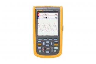
기기명 (Instrument) : 산업용 ScopeMeter™ 휴대용 오실로스코프
제작회사 (Manufacturer) : FLUKE
형식 (Model) : 120B Series (123B / 124B / 125B)
세부내용 (Description) :
주요 기능
120B 시리즈 산업용 ScopeMeter 테스트 도구에는 기술자들이 문제를 보다 빨리 해결하고 시스템을 지속적으로 가동, 운영하는 데 필요한 해답을 찾을 수 있도록 하는 혁신적인 기능이 포함되어 있습니다. Connect and View™ 트리거와 설정 기술을 사용하여 파형을 표시하고, Fluke IntellaSet™ 기술을 사용하여 관련 측정 숫자를 자동으로 볼 수 있습니다. 측정을 수동으로 조정할 필요가 없습니다. Recorder Event Detect 기능을 사용하면 파악하기 힘든 간헐적 이벤트를 캡처 및 기록하여 쉽게 보고 분석할 수 있습니다.
-. 이중 입력 디지털 오실로스코프 및 멀티미터
-. 40MHz 또는 20MHz의 오실로스코프 대역폭
-. 5,000카운트 True-rms 디지털 멀티미터 두 개
-. 손을 사용하지 않고 조작할 수 있는 Connect-and-View™ 트리거 간소화 기능
측정된 신호를 기준으로 숫자 판독값을 지능적으로 자동 조정하는 IntellaSet™ 기술
-. 오랜 기간에 걸쳐 데이터 추세를 파악하기 위한 이중 입력 파형 및 미터 판독 레코더
-. 최대 4KHz의 반복적인 파형에서 파악하기 힘든 간헐적 신호를 캡처하는 Recorder Event Detect
-. 오실로스코프, 저항 및 연속성 측정에 사용되는 차폐형 테스트 리드
-. 저항, 연속성, 다이오드 및 정전 용량 미터 측정
-. 전력 측정(W, VA, VAR, PF, DPF, Hz)
-. 전압, 전류 및 전력 고조파
-. 정의된 참조 레벨과 비교하는 BusHealth 물리적 레이어 테스트를 통해 산업용 네트워크 점검
-. 데이터/기기 설정 저장 또는 복구
-. 일상적인 유지보수나 주로 사용되는 테스트 절차를 테스트 시퀀스로 지정하여 기기 설정에 저장
-. 스코프 또는 미터 데이터를 전송, 보관 및 분석하기 위한 외부 광 절연식 USB 인터페이스
-. 내부 USB 포트에 연결되어 정보를 PC, 노트북 또는 Fluke Connect® 모바일 앱으로 무선 전송하는 WiFi 어댑터(옵션)*
-. Windows®용 FlukeView® ScopeMeter® 소프트웨어
-. 3g의 진동과 30g의 충격을 견디고 EN/IEC60529에 따라 IP51 등급을 받은 견고한 설계
-. 업계 최고의 안전 등급: CAT IV 600V의 안전 등급
-. 재충전 가능한 리튬 이온 배터리, 7시간 작동(4시간 충전)
제품 개요: Fluke 120B 시리즈 산업용 ScopeMeter™ 휴대용 오실로스코프
간소화된 테스트, 더 많은 정보와 신속한 전기기계 장비 문제 해결
컴팩트한 ScopeMeter™ 120B 시리즈는 산업용 전기 및 전기기계 장비 문제 해결/유지보수 분야에서 사용할 수 있는 견고한 오실로스코프 솔루션입니다. 오실로스코프 기능은 물론 멀티미터와 고속 레코더 기능이 하나의 기기에 포함되어 있어 간편하게 사용할 수 있는 진정한 통합형 테스트 장비입니다. 또한 ScopeMeter 120B 시리즈는 Fluke Connect™ 모바일 앱 및 스코프미터용 FlukeView™소프트웨어와 통합되어 더 많은 협업과 데이터 분석을 지원하고 중요한 테스트 정보를 저장할 수 있습니다.
제품 사양: Fluke 120B 시리즈 산업용 ScopeMeter™ 휴대용 오실로스코프
테스트 리드CatIV, 최대 전압 750VrmsCatIV, 750Vrms 최대 400Hz
|
오실로스코프 모드 |
||
|
수직 |
||
|
주파수 응답 - DC 커플링 방식 |
프로브와 테스트 리드가 없는 경우(BB120 포함) |
123B: DC~20MHz(-3dB) |
|
STL120-IV 1:1 차폐형 테스트 리드가 있는 경우 |
DC에서 12.5MHz까지 (-3dB) / DC에서 20MHz까지 (-6dB) |
|
|
VP41 10:1 프로브가 있는 경우 |
123B: DC~20MHz(-3dB) |
|
|
주파수 응답 - AC 커플링 방식 (롤오프의 경우) |
프로브와 테스트 리드가 없는 경우 |
<10Hz (-3dB) |
|
STL120-IV 1:1 차폐형 테스트 리드가 있는 경우 |
<10Hz (-3dB) |
|
|
VP41 10:1 프로브가 있는 경우 |
<10Hz (-3dB) |
|
|
상승 시간, 프로브 제외 |
123B <17.5ns |
|
|
입력 임피던스 |
프로브와 테스트 리드가 없는 경우 |
1MΩ//20pF |
|
BB120가 있는 경우 |
1MΩ//24pF |
|
|
STL120-IV 1:1 차폐형 테스트 리드가 있는 경우 |
1MΩ//230pF |
|
|
VP41 10:1 프로브가 있는 경우 |
5MΩ//15.5pF |
|
|
감도 |
5mV~200V/div |
|
|
아날로그 대역폭 리미터 |
10 kHz |
|
|
디스플레이 모드 |
A, -A, B, -B |
|
|
최대 입력 전압 A 및 B |
테스트 리드 또는 VP41 프로브를 직접 사용 |
600Vrms |
|
BB120가 있는 경우 |
600Vrms |
|
|
최대 부동 전압, 단자부터 접지까지 |
600Vrms |
|
|
수평 |
||
|
스코프 모드 |
정상, 단일, 롤 |
|
|
범위(정상) |
등가 샘플링 |
123B: 20ns ~ 500ns/div, |
|
124B 및 125B: 10ns ~ 500ns/div |
||
|
실시간 샘플링 |
1μs~5 s/div |
|
|
단일 (실시간) |
1μs~5s/div |
|
|
롤 (실시간) |
1s~60s/div |
|
|
샘플링 속도 (양쪽 채널에 동시에) |
등가 샘플링 (반복적 신호) |
최대 4GS/s |
|
실시간 샘플링 1μs~60s/div |
40MS/s |
|
|
트리거 |
||
|
화면 업데이트 |
Free run, on trigger |
|
|
소스 |
A, B |
|
|
감도 A와 B |
@ DC~5MHz |
0.5 디비전 또는 5mV |
|
기준: 40MHz |
123B: 4개 분할 |
|
|
124B 및 125B: 1.5개 분할 |
||
|
기준: 60MHz |
123B: 해당 없음 |
|
|
124B 및 125B: 4개 분할 |
||
|
기울기 |
양극, 음극 |
|
|
고급 스코프 기능 |
||
|
디스플레이 모드 |
Normal |
최대 25ns의 글리치를 캡처하고 아날로그 같은 지속적인 파형을 표시합니다. |
|
Smooth |
파형에서 발생하는 노이즈를 억제합니다. |
|
|
글리치 오프 |
샘플 간에 글리치를 캡처하지 않습니다. |
|
|
Envelope |
시간의 경과에 따라 파형의 최소값과 최대값을 기록하고 표시합니다. |
|
|
자동 설정 (Connect-and-View™) |
진폭, 시간 기준, 트리거 레벨, 트리거 갭 및 홀드 오프를 완전 자동으로 지속적으로 조정합니다. 진폭, 시간 기준 또는 트리거 레벨을 사용자가 조정하여 수동으로 덮어씁니다. |
|
추가합니다. 화면에 파형 기간이 둘 이상 표시되어야 합니다.
|
이중 입력 미터 |
|
모든 측정의 정확도는 18°C ~ 28°C 범위에서 ±(판독값의 % + 카운트 수) 이내입니다. |
|
18°C 이하나 28°C 이상의 각 C에 0.1x(비정확도)를 추가합니다. 10:1 프로브로 전압을 측정할 때는 +1%의 프로브 불확도를 |
|
입력 A 및 입력 B |
||
|
DC 전압 (VDC) |
||
|
범위 |
500mV, 5V, 50V, 500V, 750V |
|
|
정확도 |
±(0.5% +5카운트) |
|
|
공통 모드 거부율 (CMRR) |
>100 dB @ dc, >60dB @ 50, 60 또는 400Hz |
|
|
풀 스케일 판독값 |
5000 카운트 |
|
|
True-RMS 전압 (V ac 및 V ac+dc) |
||
|
범위 |
500mV, 5V, 50V, 500V, 750V |
|
|
5%~100% 범위에 대한 정확도 (DC 커플링 방식) |
DC에서 60Hz까지 (V ac+dc) |
±(1% +10카운트) |
|
1Hz~60Hz (V ac) |
±(1% +10카운트) |
|
|
5%~100% 범위에 대한 정확도 (AC 또는 DC 커플링 방식) |
60 Hz ~ 20 kHz |
±(2.5% +15카운트) |
|
DC 거부 (VAC만 해당) |
>50dB |
|
|
공통 모드 거부율 (CMRR) |
>100dB @ dc |
|
|
> 60dB(50Hz, 60Hz, 400Hz) |
||
|
풀 스케일 판독값 |
5000 카운트, 판독은 모든 신호 파고율에 무관합니다. |
|
|
피크 |
||
|
모드 |
최대 피크, 최소 피크, 또는 피크-피크 |
|
|
범위 |
500mV, 5V, 50V, 500V, 2200V |
|
|
정확도 |
정확도 최대 피크 또는 최소 피크 |
전체 스케일의 5% |
|
정확도 피크-피크 |
전체 스케일의 10% |
|
|
풀 스케일 판독값 |
500카운트 |
|
|
주파수(Hz) |
||
|
범위 |
123B: 1Hz, 10Hz, 100Hz, 1kHz, 10kHz, 100kHz,1MHz, 10MHz, 50MHz |
|
|
124B 및 125B: 1Hz, 10Hz, 100Hz, 1kHz, 10kHz, 100kHz,1MHz, 10MHz, 70MHz |
||
|
주파수 범위 |
연속 자동 설정에서 15Hz (1Hz)~50MHz |
|
|
정확도 @1Hz~1MHz |
±(0.5% +2카운트) |
|
|
풀 스케일 판독값 |
10,000 카운트 |
|
|
RPM |
||
|
최대 판독값 |
50.00kRPM |
|
|
정확도 |
±(0.5% +2카운트) |
|
|
작동 사이클(PULSE) |
||
|
범위 |
2% ~ 98% |
|
|
주파수 범위 |
연속 자동 설정에서 15Hz (1Hz)~30MHz |
|
|
펄스 폭(PULSE) |
||
|
주파수 범위 |
연속 자동 설정에서 15Hz (1Hz)~30MHz |
|
|
풀 스케일 판독값 |
1000카운트 |
|
|
암페어(AMP) |
||
|
전류 클램프를 사용하는 경우 |
범위 |
V dc, V ac, V ac+dc 또는 PEAK와 같음 |
|
배율 |
0.1mV/A, 1mV/A, 10mV/A, 100mV/A, 400mV/A, 1V/A, 10mV/mA |
|
|
정확도 |
V dc, V ac, V ac+dc 또는 PEAK와 같음(전류 클램프 불확도 추가) |
|
|
온도 프로브(선택 사항)를 사용하는 경우의 온도(TEMP) |
||
|
범위 |
200°C/div (200°F/div) |
|
|
배율 |
1mV/°C 및 1mV/°F |
|
|
정확도 |
V dc와 같음(온도 프로브 불확도 추가) |
|
|
데시벨(dB) |
||
|
0dBV |
1V |
|
|
0dBm (600Ω /50Ω) |
600Ω 또는 50Ω 기준 1mW |
|
|
dB 기준 |
V dc, V ac 또는 Vac+dc |
|
|
풀 스케일 판독값 |
1000카운트 |
|
|
파고율(CREST) |
||
|
범위 |
1 ~ 10 |
|
|
풀 스케일 판독값 |
90카운트 |
|
|
상 |
||
|
모드 |
A~B, B~A |
|
|
범위 |
0~359도 |
|
|
해상도 |
1도 |
|
|
전력(125B만 해당) |
||
|
구성 |
1상/3상 3도체 균형 부하(3상: 기본 요소만 해당, 자동 설정 모드만) |
|
|
역률(PF) |
와트와 VA 범위 간 비율 - 0.00~1.00 |
|
|
와트 |
입력 A(볼트)와 입력 B(암페어)의 해당 샘플들을 곱한 RMS 판독값 |
|
|
풀 스케일 판독값 |
999카운트 |
|
|
VA |
Vrms x Arms |
|
|
풀 스케일 판독값 |
999카운트 |
|
|
VA 상대값(var) |
√((VA)²-W²) |
|
|
풀 스케일 판독값 |
999카운트 |
|
|
Vpwm |
||
|
용도 |
모터 드라이브 인버터 출력처럼 펄스 폭 변조 신호에서 측정 |
|
|
원리 |
기본 주파수의 모든 기간에서 샘플 평균값을 기준으로 한 유효 전압이 판독값에 나타납니다. |
|
|
정확도 |
사인파 신호에 대한 Vrms로 표시 |
|
|
입력 A ~ 공통 |
||
|
옴(Ω) |
||
|
범위 |
123B 및 124B |
500Ω , 5kΩ, 50kΩ, 500kΩ, 5MΩ, 30MΩ |
|
125B |
50Ω, 500Ω , 5kΩ, 50kΩ, 500kΩ, 5MΩ, 30MΩ |
|
|
정확도 |
±(0.6% + 5카운트) 50Ω ±(2% + 20카운트) |
|
|
풀 스케일 판독값 |
50Ω~5MΩ - 5000 카운트, 30MΩ - 3000 카운트 |
|
|
측정 전류 |
0.5mA~50nA, 범위 증가에 따라 감소 |
|
|
개방 회로 전압 |
<4V |
|
|
연속성(Cont) |
||
|
신호음 |
50Ω 범위에서 < (30Ω ± 5Ω) |
|
|
측정 전류 |
0.5 mA |
|
|
단락 감지 |
≥1 ms |
|
|
다이오드 |
||
|
측정 전압 |
@0.5mA |
> 2.8V |
|
@개방 회로 |
<4V |
|
|
측정 전류 |
0.5 mA |
|
|
극성 |
+ 입력 A 기준, - COM 기준 |
|
|
정전 용량(CAP) |
||
|
범위 |
50nF, 500nF, 5μF, 50μF, 500μF |
|
|
풀 스케일 판독값 |
5000 카운트 |
|
|
측정 전류 |
500 nA~0.5 mA, 범위 증가에 따라 증가 |
|
|
고급 미터 기능 |
|
|
영점 설정 |
실제값을 기준으로 설정 |
|
AutoHold(A 기준) |
안정적인 측정 결과를 캡처하여 고정합니다. 안정되었을 때 경고음이 울립니다. AutoHold는 주 미터 판독값에서 작용하며 임계값은 AC 신호의 경우에는 1Vpp이고 DC 신호의 경우에는 100mV입니다. |
|
고정 소수점 |
감쇠 키를 사용하여 활성화합니다. |
자동 레벨링만 가능)
|
커서 판독(124B 및 125B) |
|
|
소스 |
A, B |
|
단일 수직선 |
평균, 최소 및 최대 판독값 |
|
평균, 최소, 최대 및 판독을 시작한 이후의 시간 (롤 모드에서, 보류 상태의 기기) |
|
|
최소, 최대 및 판독을 시작한 이후의 시간 (레코더 모드에서, 보류 상태의 기기) |
|
|
전력 품질 모드에서의 고조파 값. |
|
|
이중 수직선 |
피크-피크, 시간 거리와 역방향 시간 거리 판독 |
|
평균, 최소, 최대 및 시간 거리 판독 (롤 모드에서, 보류 상태의 기기) |
|
|
이중 수평선 |
고, 저 및 피크-피크 판독 |
|
상승 또는 하강 시간 |
전이 시간, 0% 수준 및 100% 수준 판독(수동 또는 자동 레벨링, 단일 채널 모드에서는 |
|
정확도 |
오실로스코프 정확도와 같음 |
|
레코더 |
|
|
레코더는 미터 레코더 모드에서 미터 판독값을 캡처하거나 스코프 레코더 모드에서 파형 샘플을 연속적으로 캡처합니다. 정보는 내부 메모리나 옵션의 SD 카드 (125B나 124B만 해당)에 저장됩니다. |
|
|
결과는 시간의 경과에 따른 미터 측정의 최소값과 최대값의 그래프를 나타내는 차트 레코더 디스플레이로 표시되거나 모든 캡처된 샘플의 좌표를 나타내는 파형 레코더 디스플레이로 표시됩니다. |
|
|
계측 수치 |
|
|
측정 속도 |
최대 초당 2회 측정 |
|
레코드 크기 (최소, 최대, 평균) |
1 채널에 대해 2M 판독 |
|
기록 시간 범위 |
2주 |
|
최대 이벤트 수 |
1024 |
|
파형 기록 |
|
|
최대 샘플링 속도 |
초당 400K 샘플 |
|
크기(내부 메모리) |
400M 샘플 레코딩 시간 |
|
시간축(내부 메모리) |
500μs/div에서 15분 |
|
레코드 크기(SD 카드) |
1.5G 샘플 |
|
레코딩 시간축(SD 카드) |
500μs/div에서 11시간 |
|
최대 이벤트 수 |
64 |
(기본 40Hz~70Hz)
|
전력 품질(125B만 해당) |
||
|
판독값 |
Watt, VA, var, PF, DPF, Hz |
|
|
Watt, VA, var 범위(자동) |
250W~250 MW, 625MW, 1.56GW |
|
|
선택 시: 총계(%r) |
±(2% + 6카운트) |
|
|
선택 시: 기본(% f) |
±(4% + 4 카운트) |
|
|
DPF |
0.00 ~ 1.00 |
|
|
PF |
0.00~1.00, ±0.04 |
|
|
주파수 범위 |
10.0 Hz~15.0 kHz |
|
|
고조파 수 |
DC에서 51까지 |
|
|
판독값/커서 판독값 |
Vrms/Arms/Watt |
기본의 각 고조파를 개별 판독값에 대해 선택할 수 있음 |
|
기본, 위상 각도 및 K 계수의 주파수를 포함(암페어 및 와트 단위) |
||
|
BusHealth 테스터(Fluke 125B만 해당) |
||
|
유형 |
하위 유형 |
프로토콜 |
|
AS-i |
NEN-EN50295 |
|
|
CAN |
ISO-11898 |
|
|
Interbus S |
RS-422 |
EIA-422 |
|
Modbus |
RS-232 |
RS-232/EIA-232 |
|
RS-485 |
RS-485/EIA-485 |
|
|
Foundation fieldbus |
H1 |
61158 type 1, 31.25kBit |
|
Profibus |
DP |
EIA-485 |
|
PA |
61158 유형 1 |
|
테스트 장비를 켠 상태에서 7시간 (화면 파형 및 설정) (최대 크기 32GB)
(10.2 x 5.2 x 2.15인치)소프트웨어 사용
|
기타 |
||
|
디스플레이 |
유형 |
5.7인치 컬러 활성 매트릭스 TFT |
|
해상도 |
640 x 480픽셀 |
|
|
파형 디스플레이 |
수직 |
40픽셀에서 10개 분할 |
|
수평 |
40픽셀에서 12개 분할 |
|
|
전원 |
외부 |
전원 어댑터 BC430 사용 |
|
입력 전압 |
10V DC~21V DC |
|
|
전력 소비량 |
5W 일반 |
|
|
입력 커넥터 |
5mm 잭 |
|
|
내부 |
배터리 팩 BP290 사용 |
|
|
배터리 전원 |
재충전 가능한 리튬 이온 10.8V |
|
|
작동 시간 |
백라이트 밝기를 50%로 했을 때 7시간 |
|
|
충전 시간 |
테스트 장비를 끈 상태에서 4시간 |
|
|
허용되는 주변 온도 |
충전 중 0~40°C (32~104°F) |
|
|
메모리 |
내부 메모리에 20개 데이터 세트를 저장할 수 있음 |
마이크로 SD 카드 슬롯(SD 카드는 옵션) |
|
공학적 |
크기 |
259 x 132 x 55 mm |
|
중량 |
1.4kg (3.2lb)(배터리 팩 포함) |
|
|
인터페이스 |
광 절연식 |
화면 복사본(비트맵), 설정 및 데이터 전송 |
|
USB에서 PC/노트북으로 |
OC4USB 광 절연식 USB 어댑터/케이블, (옵션), Windows®용 FlukeView® |
|
|
옵션 WiFi 어댑터 |
화면 복사본(비트맵), 설정 및 데이터를 PC/랩톱, 태블릿, 스마트폰 등에 빠르게 전송 USB 포트가 제공되어 WiFi 동글을 부착할 수 있습니다. 안전상의 이유로 케이블이 있는 USB 포트는 사용하면 안 됩니다. |
|
그룹 1, Class AIV, 750Vrms 최대 400 Hz
|
환경 |
||
|
환경 |
MIL-PRF-28800F, Class 2 |
|
|
온도 |
배터리 작동 |
0 ~ 40 °C(32 ~ 104 °F) |
|
전원 어댑터 작동 |
0 ~ 50 °C(32 ~ 122 °F) |
|
|
보관 |
-20 ~ 60 °C(-4 ~ 140 °F) |
|
|
습도(작동) |
@ 0~10°C(32~50°F) |
비응축 |
|
@ 10~30°C(50~86°F) |
95% |
|
|
@ 30~40°C(86~104°F) |
75% |
|
|
@ 40~50°C(104~122°F) |
45% |
|
|
보관 |
@ -20~60°C(-4~140°F) |
비응축 |
|
고도 |
3km(10,000피트)에서 작동 |
CAT III 600V |
|
2km(6,600피트)에서 작동 |
CAT IV 600V |
|
|
보관 |
12km(40,000피트) |
|
|
EMC 전자기 호환성 |
국제 |
IEC 61326-1: 산업, CISPR 11: |
|
대한민국(KCC) |
Class A 장비(산업 방송 및 통신 장비) |
|
|
미국(FCC) |
47 CFR 15 subpart B, 이 제품은 15.103항에 따라 예외 장치로 간주됨 |
|
|
어댑터를 통한 무선 기능 |
주파수 범위 |
2412MHz ~ 2462MHz |
|
출력 전압 |
<100mW |
|
|
외함 보호 |
IP51, 참조: EN/IEC60529 |
|
|
안전 |
일반 |
IEC 61010-1: 오염도 2 |
|
측정 |
IEC 61010-2-033: CAT IV 600V/CAT III 750V |
|
|
최대 입력 전압 입력 A 및 B |
직접 입력 또는 리드 사용 |
저감 시 600Vrms CAT IV |
|
바나나 대 BNC 어댑터 BB120이 있는 경우 |
저감 시 600Vrms |
|
|
단자로부터 접지까지의 최대 부동 전압 |
600Vrms Cat |
|
첨부 (Attach)
파일내용 (The content of file) :
-. 기술 자료 (Data Sheet) :
-. 안전 정보 :
-. 사용자 설명서 (User's Manual) :
-. 사용자 설명서 보충자료 (Manual Supplement) :
-. Calibration Manual (교정 설명서) :
-. Calibration Manual Supplement (교정 설명서 보충자료) :
사진 (Picture) :
'사용설명서' 카테고리의 다른 글
| Yokogwa / 700925_차동프로브 (DIFFERENTIAL PROBE) 15MHz/1000V (0) | 2020.07.21 |
|---|---|
| Tektronix / AFG3000C serise_임의/함수 발생기 (Arbitrary/Function Generators) (0) | 2020.07.21 |
| KEITHLEY / 428_Programmable Current Amplifier (0) | 2020.07.21 |
| Keysight (Agilent) / MSO6054A_혼합 신호 오실로스코프: 500 MHz, 아날로그 4채널 + 디지털 16채널 (2) | 2020.07.20 |
| Keysight / DSO-X 3024 T_오실로스코프: 200 MHz, 아날로그 4채널 (0) | 2020.07.20 |
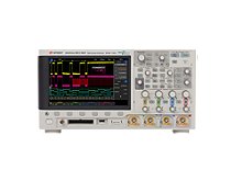
기기명 (Instrument) : Mixed Signal Oscilloscope (혼합 신호 오실로스코프) : 500 MHz, 아날로그 4채널 + 디지털 16채널
제작회사 (Manufacturer) : Keysight ;키사이트 (Agilent ;애질런트)
형식 (Model) : MSO6054A
6000 Series Oscilloscopes
|
Model DSO6012A MSO6012A DSO6014A MSO6014A DSO6032A MSO6032A DSO6034A MSO6034A DSO6052A MSO6052A DSO6054A MSO6054A DSO6102A MSO6102A DSO6104A MSO6104A |
Bandwidth 100 MHz 100 MHz 100 MHz 100 MHz 300 MHz 300 MHz 300 MHz 300 MHz 500 MHz 500 MHz 500 MHz 500 MHz 1 GHz 1 GHz 1 GHz 1 GHz |
Maximum sample rate 2 GSa/s 2 GSa/s 2 GSa/s 2 GSa/s 2 GSa/s 2 GSa/s 2 GSa/s 2 GSa/s 4 GSa/s 4 GSa/s 4 GSa/s 4 GSa/s 4 GSa/s 4 GSa/s 4 GSa/s 4 GSa/s |
Memory depth 8 Mpts 8 Mpts 8 Mpts 8 Mpts 8 Mpts 8 Mpts 8 Mpts 8 Mpts 8 Mpts 8 Mpts 8 Mpts 8 Mpts 8 Mpts 8 Mpts 8 Mpts 8 Mpts |
Scope channels 2 2 4 4 2 2 4 4 2 2 4 4 2 2 4 4 |
Logic channels
16
16
16
16
16
16
16
16 |
세부내용 (Description) :
주요 특징 및 기능
-. 500 MHz
-. 아날로그 4채널 + 디지털 16채널
-. 4 GSa/s의 샘플링 속도로 가장 포착하기 어려운 문제 식별
-. 최대 8 Mpts의 딥 메모리로 높은 샘플링 속도를 유지하면서 긴 신호를 간 -. 편하게 포착
-. 100,000 wfms/s의 파형 업데이트 속도로 간헐적인 문제를 빠르게 탐색
-. 맞춤 제작된 소프트웨어로 FPGA를 더 빠르게 분석하고 디버그
-. 표준 USB, LAN, GPIB, XGA 출력 및 LXI 호환 커넥티비티로 간편하게 연결
-. 배터리 파워 옵션만으로 더 많은 장소에서 측정
사양
|
대역폭 |
500 MHz |
|
대역폭 업그레이드 |
해당 없음 |
|
채널 |
4 + 16 |
|
최대 메모리 깊이 |
8 Mpts |
|
최대 샘플링 속도 |
4 GSa/s |
|
디스플레이 크기 |
6.3 인치 |
|
파형 업데이트 속도 |
100,000 wfms/s |
|
ADC 비트 |
8비트 |
|
내장 계측기(옵션) |
해당 없음 |
|
프로토콜 트리거 및 디코드 |
옵션 |
|
운영 체제 |
임베디드 |
|
리얼타임 |
예 |
첨부 (Attach)
파일내용 (The content of file) :
-. Data Sheet (데이터시트) :
-. 사용자를 위한 빠르고 쉬운 안내서 (Quick Guide) :
-. Service Guide (서비스 가이드) :
사진 (Picture) :

'사용설명서' 카테고리의 다른 글
| FLUKE / 120B Series_산업용 ScopeMeter™ 휴대용 오실로스코프 (0) | 2020.07.21 |
|---|---|
| KEITHLEY / 428_Programmable Current Amplifier (0) | 2020.07.21 |
| Keysight / DSO-X 3024 T_오실로스코프: 200 MHz, 아날로그 4채널 (0) | 2020.07.20 |
| Yokogawa / WT300E_World Best Power Meter (0) | 2020.07.20 |
| Fluke / 175, 177, 179_True-RMS 디지털 멀티미터 (0) | 2020.07.20 |
기기명 (Instrument) : 오실로스코프 (Digital Oscilloscope)
제작회사 (Manufacturer) : Keysight (키사이트)
형식 (Model) : DSO-X 3024 T
InfiniiVision 3000T X 시리즈
InfiniiVision 3000T X 시리즈 오실로스코프 모델 , 대역폭 , 샘플링 속도
|
대역폭 |
100 MHz |
200 MHz |
350 MHz |
500 MHz |
1 GHz |
|
샘플링 속도 (인터리빙, 비인터리빙) |
5 GSa/s, 2.5 GSa/s |
5 GSa/s, 2.5 GSa/s |
5 GSa/s, 2.5 GSa/s |
5 GSa/s, 2.5 GSa/s |
5 GSa/s, 2.5 GSa/s |
|
2 채널 + 16 로직채널 MSO |
MSO-X 3012 T |
MSO-X 3022 T |
MSO-X 3032 T |
MSO-X 3052 T |
MSO-X 3102 T |
|
4 채널 + 16 로직채널 MSO |
MSO-X 3014 T |
MSO-X 3024 T |
MSO-X 3034 T |
MSO-X 3054 T |
MSO-X 3104 T |
|
2 채널 DSO |
DSO-X 3012 T |
DSO-X 3022 T |
DSO-X 3032 T |
DSO-X 3052 T |
DSO-X 3102 T |
|
4 채널 DSO |
DSO-X 3014 T |
DSO-X 3024 T |
DSO-X 3034 T |
DSO-X 3054 T |
DSO-X 3104 T |
세부내용 (Description) :
주요 특징 및 기능
-. 200 MHz
-. 아날로그 4채널
-. 8.5인치의 대형 정전식 터치 스크린으로 간편하게 신호를 확인하고 분석
-. 독점 기능인 Zone 터치 트리거링으로 수 초 내에 신호를 분리
-. 1,000,000 wfms/s의 업데이트 속도로 더 많은 신호를 상세하게 확인
-. 최대 4 Mpts의 메모리로 더 많은 데이터 수집
-. 본체 구매 후, 모든 옵션 별도 업그레이드 가능. 간편하게 측정기능 확장: 대역폭, 디지털 채널, 20 MHz 임의 파형 발생기, 3디지트 전압계, 시리얼 트리거와 분석, 그리고 마스크 테스트 기능 언제든지 추가
첨부 (Attach)
파일내용 (The content of file) :
-. Product Fact Sheet :
-. 데이터 시트 (Data Sheet) :
-. 사용설명서 (User's Manual) :
사진 (Picture) :
'사용설명서' 카테고리의 다른 글
| KEITHLEY / 428_Programmable Current Amplifier (0) | 2020.07.21 |
|---|---|
| Keysight (Agilent) / MSO6054A_혼합 신호 오실로스코프: 500 MHz, 아날로그 4채널 + 디지털 16채널 (2) | 2020.07.20 |
| Yokogawa / WT300E_World Best Power Meter (0) | 2020.07.20 |
| Fluke / 175, 177, 179_True-RMS 디지털 멀티미터 (0) | 2020.07.20 |
| UNI-T / UT61 Series_Modern Digital Multimeter (0) | 2020.07.20 |
기기명 (Instrument) : Oscilloscope (파형측정기)
제작회사 (Manufacturer) : IWATSU
형식 (Model) : SS-5710
세부내용 (Description) :
The SS-5710 is useful in a wide range of applications for not only production lines and maintenance and service purposes but also for the research and development of a variety of electronic devices. It has an ADD function for measuring the sum of two signals and CH 2 Polar for measurement of the difference between two signals. It has delayed swep, single sweep, ALT sweep, and X-Y operation functions, and a TV synchcronizing signal separator circuit so that TV and other composite video signal waveforms can be observed.
• Bandwidth: 60 MHz
• Analog Channels: 4
• Operating System: Embedded
• Form Factor: Benchtop
첨부 (Attach)
파일내용 (The content of file) : Instruction Manual
사진 (Picture) :

'사용설명서' 카테고리의 다른 글
| TESTO / 174T, 174H_1채널 미니 온도 로거, 2채널 미니 온습도 로거 (0) | 2020.07.13 |
|---|---|
| IET LABS., Inc (General Radio_GenRad) / 1433 series_Decade Resistor (0) | 2020.07.13 |
| ITECH / IT9121, IT9121E_AC/DC Power meter (0) | 2020.07.06 |
| KANOMAX / 3887_Handheld Laser Particle Counter (분진측정기) (0) | 2020.07.06 |
| Yokogawa / GX10, GX20, GP10, GP20_Touch Screen (0) | 2020.07.02 |