기기명 (Instrument) : AC Voltage Current Standard (교류 전압 전류 교정기)
제작회사 (Manufacturer) : YOKOGAWA (요꼬가와)
형식 (Model) : 2558A
세부내용 (Description) :
The 2558A is a cost-effective, high-precision instrument capable of outputting a wide range of AC voltages and currents for the calibration of AC measurement devices such as analog wattmeters, power meters, clamp-on testers, and current transformers. Intuitive front panel controls and various computer interfaces enable the 2558A to be operated manually or become integrated into an larger system.
FEATURES
The 2558A AC Voltage Current Standard offers users the best-in-class functionality and reliability customers have come to trust from Yokogawa.
A suite of features for verification and testing of AC measuring devices
· Voltage, Current, and Frequency sweeping
· Output Divider
· Direct Readout of the Deviation
· Digital Display of Output
· Common Current Output Terminals
Go beyond conventional accuracy and output standards
The wide output ranges of 1.00 mV to 1200.0 V AC and 1.00 mA to 60.00 A AC mean that the 2558A is the instrument of choice for the cost effective calibration of AC analog meters. Rotary controls and a range of computer interfaces enable the 2558A to be intuitively operated through the frontpanel or controlled by an ATE system.
High Accuracy
AC Voltage: +/- 0.04 %
AC Current: +/- 0.05 %
The 2558A AC Voltage Current Standard is more than sufficient to calibrate meters with a class 0.1 % accuracy.
|
10 to 120 % of range |
|||
|
+/- (% of setting + % of range) |
|||
|
|
50/60 Hz |
40 ≤ f ≤ 400 Hz |
400 |
|
AC Voltage |
0.03 + 0.01* |
0.05 + 0.01 |
0.10 + 0.02 |
|
AC Current |
0.04 + 0.01* |
0.06 + 0.01 |
0.12 + 0.02 |
* Add 0.1% of range when output is 120% to 144%.
|
1 to 10% of range |
|||
|
+/- (% of range) |
|||
|
|
50/60 Hz |
40 ≤ f ≤ 400 Hz |
400 |
|
AC Voltage |
0.013 |
0.015 |
0.03 |
|
AC Current |
0.014 |
0.016 |
0.032 |
High Stability
AC Voltage/Current: +/- 50 ppm/h
+/- (20 ppm of range + 30 ppm of range)/h
Perform measurements with high repeatability over time
Wide Output Range
AC Voltage: 1.00 mV to 1200.0 V
AC Current: 1.00 mA to 60.00 A
6 voltage ranges (100 m/1/10/100/300/1000 ([V]))
4 current ranges (100 m/1/10/50 ([A]))
The generation range is 0 to 144 % of range
Wide Frequency Range
40 to 1000 Hz (Frequency accuracy: +/- 50 ppm)
The 2558A provides fixed frequencies of 50/60 Hz (commercial) and 400 Hz (marine and aviation), as well as variable frequencies from 40 to 1000 Hz.
The high frequency accuracy of the 2558A (50 ppm) also enables it to be used to calibrate frequency meters.
Multiple 2558A units can be synchronized using the internal phase shifter. This means that two 2558As can be used as accurate sources of voltage and current for calibrating power meters.
APPLICATION
Calibration & Meter Testing
The 2558A provides specific functions to enable meters to be calibrated accurately and efficiently.
Using the output divider and deviation
Calibrating two or more points is quick and simple. It is only necessary to preselect the number of required calibration points with the lower divider control and then use the upper control to step the output to the next calibration point. The deviation settings will then enable the output value and error of each calibration point to be displayed directly.
The deviation preset control can be used to move the output value in small increments (2 or 5 % of the step between calibration points).
This means that it is possible to finely approach the target calibration point, either from a lower value or a higher one, without exceeding it. This is particularly useful when the friction (hysteresis) of the moving part needs to be taken into consideration. In this case, the point is calibrated twice, once from a lower value and once more from a higher value and the final calibration result is the average of the two.
Using sweep
Needle sticking tests can be performed with high repeatability. It is possible to stop at any point and sweep around it in fine detail.
Power Calibration
A power calibration system can be created by using two 2558As (one each for AC voltage and AC current) together with a Yokogawa WT3000 power analyzer as the reference.
One of the 2558As acts as the master unit and provides the synchronizing oscillator signal. The required power factors is set by adjusting the phase shifter on the slave unit and monitoring the result on the WT3000. A 3 phase power calibrator system can be simply built by adding further 2558As.
Higher Current Output
To generate higher current than 72 A, two 2558As can be connected to double the output to 144 A.
Condition:
· Accuracy, stability, temperature coefficient is the sum of the individual units.
· 50/60 Hz only.
Use Existing 2558 Programs
The 2558A is backwardly compatible with the previous 2558 Model. The new 2558A supports a 2558 command mode, which means that you can switch from the 2558 to the 2558A without modifying your program. It is also possible to mix 2558s and new 2558As in the same system.
Comparison with the 2558
|
|
|
2558A |
2558 |
|
AC Voltage |
Output range of the specified accuracy |
1.00 mV to 1200.0 V |
1.00 mV to 1200.0 V |
|
Accuracy (50/60 Hz) |
+/- 400 ppm |
+/- 950 ppm |
|
|
Frequency of the specified accuracy |
40 to 1000 Hz |
50 /60 /400 Hz |
|
|
AC Current |
Output range of the specified accuracy |
1.00 mA to 60.00 A |
1.00 mA to 60.00 A |
|
Accuracy (50/60 Hz) |
+/- 500 ppm |
+/- 950 ppm |
|
|
Frequency of the specified accuracy |
40 to 1000 Hz |
50 /60 /400 Hz |
|
|
Frequency |
Output range |
40 to 1000 Hz |
40 to 500 Hz |
|
Accuracy |
+/- 50 ppm |
+/- 1% |
|
|
Max. Output |
Approx. 36 VA (60 A/0.6 V) |
Approx. 36 VA (60 A/0.6 V) |
|
|
Stability |
+/- (20 ppm of setting + 30 ppm of range)/h |
+/- (0.03% of range)/h |
|
|
Dimensions (mm) |
426 (W) x 132 (H) x 400 (D) |
439 (W) x 149 (H) x 415 (D) |
|
SPECIFICATION
Front of Unit Specifications
Back of Unit Specifications
Output
|
Range |
Output Range |
Specified Output Range* |
Resolution |
Maximum Output |
|
100 mV |
0 to 144.00 mV |
1 to 120.00 mV |
10 uV |
--- |
|
1 V |
0 to 144.00 mV |
0.01 to 1.2000 V |
100 uV |
0.5 A or more |
|
10 V |
0 to 14.400 V |
0.1 to 12.000 V |
1 mV |
Approx. 3 A |
|
100 V |
0 to 144.00 V |
1 to 120.00 V |
10 mV |
Approx. 0.3 A |
|
300 V |
0 to 432.0 V |
3 to 360.0 V |
100 mV |
Approx. 0.1 A |
|
1000 V |
0 to 1440.0 V |
10 to 1200.0 V |
100 mV |
Approx. 6 mA |
|
100 mA |
0 to 144.00 mA |
1 to 120.00 mA |
10 uA |
Approx. 15 V |
|
1 A |
0 to 1.4400 A |
0.01 to 1.2000 A |
100 uA |
Approx. 15 V |
|
10 A |
0 to 14.400 A |
0.1 to 12.000 A |
1 mA |
Approx. 3 V |
|
50 A |
0 to 72.00 A |
0.5 to 60.00 A |
10 mA |
Approx. 0.6 V |
* 1% to 144% of range when frequency is 50 or 60 Hz.
Accuracy
|
|
Upper: 180 Days Lower: 1 Year |
|||||
|
|
10 % to 120% of range |
1% to 10% of range |
||||
|
|
+/- (% of setting + % of range) |
+/- (% of range) |
||||
|
Range |
50/60 Hz |
40 Hz ≤ f ≤ 400 Hz |
400 Hz |
50/60 Hz |
40 Hz ≤ f ≤ 400 Hz |
400 Hz |
|
100 mV |
0.03 + 0.01* 0.04 + 0.01* |
0.05 + 0.01 0.06 + 0.01 |
0.10 + 0.02 0.11 + 0.02 |
0.013 0.014 |
0.015 0.016 |
0.030 0.031 |
|
1 V |
||||||
|
10 V |
||||||
|
100 V |
||||||
|
300 V |
||||||
|
1000 V |
||||||
|
100 mA |
0.04 + 0.01* 0.055 + 0.01* |
0.06 + 0.01 0.075 + 0.01 |
0.12 + 0.02 0.135 + 0.02 |
0.014 0.0155 |
0.016 0.0175 |
0.032 0.0335 |
|
1 A |
||||||
|
10 A |
||||||
|
50 A |
||||||
* Add 0.1% of range when output is 120% to 144% of range.
첨부 (Attach)
파일내용 (The content of file) :
-. User's Manual (사용설명서) :
-. Brochure (브로셔) :
-. User's Manual(Simple Adjustment Procedure for voltage, current and Frequency) :
사진 (Picture) :

'사용설명서' 카테고리의 다른 글
| B&K (Brüel & Kjær) / 2250_SOUND LEVEL METER / ANALYZER (0) | 2020.07.23 |
|---|---|
| BENETECH / GM1352_Sound Level Meter (0) | 2020.07.23 |
| Tektronix / TDS1000 and TDS2000 Series_Oscilloscopes (0) | 2020.07.22 |
| EZ Digital(LG) / FG-7005C_Sweep / Function Generator (0) | 2020.07.21 |
| GW Instek / AFG-2225_Arbitrary Function Generator (0) | 2020.07.21 |
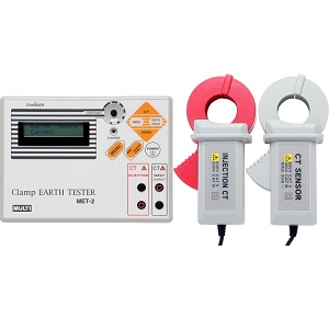
기기명 (Instrument) : Clamp Earth Tester
제작회사 (Manufacturer) : MULTI
형식 (Model) : MET-2
세부내용 (Description) :
Simple earth resistance measurements without auxiliary spikes and test leads.
FEATURES
Test frequencies are selected automatically to minimize erroneous measurements.
Earth resistance measurements for single and multi earthing systems.
Leakage current and load current measurements with 200mA, 2000mA and 20A ranges.
Data memory and auto power off function.
10Ω and 300Ω earth resistance ranges.
|
SPECIFICATIONS |
|
|
Withstanding Voltage |
AC 3700V, 1 minute (between CT core and CT handle) |
|
Insulation Resistance |
More than 100MΩ (between CT core and CT handle) |
|
Storage Temperature |
-10℃~60℃, < 80% (without condensation) |
|
Size and Weight |
Measuring CT:90.5(W)×165(H)×38(D)mm, approx.460g |
|
Operating Temperature |
0℃~40℃, < 85%RH ( without condensation) |
|
Power supply |
NiMH battery pack (1.2V x 5) |
|
Power consumption |
Approx. 380mA(Earth resistance measurement) |
|
Safety standard |
IEC 61010-1, IEC61010-2-032 |
|
Limitation of circuit voltage |
Less than 500V |
|
Accessories |
Measuring CT:1 |
|
Display |
LCD, 16 letters/characters × 2 lines |
|
Measuring function |
Earth Resistance, AC Current (Load and Leakage) |
|
A/D Conversion |
Dual slope integration mode |
|
Over range indication |
"OVER" on LCD |
|
Data hold indication |
"DH" mark on LCD |
|
Low battery indication |
"B" mark on LCD |
|
Battery life |
Approx.400 times measurements under full charged condition (Subject to the times of charging and discharging) |
|
Sampling |
Approx. 2 times/sec. for AC current |
|
Auto power off function |
Approx. 5 minutes after power on |
|
Measuring time |
Approx. 30 second for earth resistance |
|
Accuracy(Earth resistance) |
(23℃ ± 5℃, 85% RH or less) |
|
Accuracy(AC current) |
(23℃ ± 5℃, 85% RH or less) |
|
Measuring CT |
φ34mm with 2.5m lead |
|
Injection CT |
φ34mm with 2.5m lead |
|
Injection signal |
Approx. 160mVp-p, Auto sweep 4KHz~200kHz |
|
Battery charger |
AC200V~240V (50/60Hz) |
|
Memory function |
200 measuring data can be stored and displayed |
첨부 (Attach)
파일내용 (The content of file) :
#. Catalog (카달로그) :
#. Instruction Manual (사용설명서) :
사진 (Picture) :
'사용설명서' 카테고리의 다른 글
| Keysight / E4980A, E4980AL_Precision LCR Meter (20Hz ~ 2 MHz) (0) | 2020.07.15 |
|---|---|
| EXTECH / 380193_Passive Component LCR Meter (0) | 2020.07.15 |
| TESTO / 174T, 174H_1채널 미니 온도 로거, 2채널 미니 온습도 로거 (0) | 2020.07.13 |
| IET LABS., Inc (General Radio_GenRad) / 1433 series_Decade Resistor (0) | 2020.07.13 |
| IWATSU / SS-5710_Oscilloscope (0) | 2020.07.07 |
기기명 (Instrument) : 누설전류 시험기 (Leakage Currnet HiTester)
제작회사 (Manufacturer) : HIOKI (히오키)
형식 (Model) : ST5540
세부내용 (Description) :
● 의료용 전기기기 : 전기적 안전성 시험 : IEC60601-1 : 2005 Ed 3.0 JIS T 0601-1 : 2012가 강제 적용
· (※ 2012년 6월 1일 이후 EU 지역에서 판매되는 의료기기 대상) ST5540은 2017년 현재 최신 IEC 60601-1 : 2005+ A1 : 2012 (Ed 3.1) 및 IEC62353에 대응
· (※ 2017년 6월 1일 이후 일본에서 판매되는 의료기기 대상) ST5540은 2017년 현재 최신 JIS T 0601-1 : 2012 추가보충 1 : 2014에 대응
● 일반 전기기기 : 전기용품 안전법 / JIS / IEC / UL 규격에 대응
● 무정전극성 전환 기능을 탑재, 택트 타임이 대폭 감소
● 정격 전류 20A까지 대응, 신 규격 제품에도 여유 있게 대응 가능
● 대화식으로 간편하게 조작할 수 있는 터치 패널
● 통신 기능과 외부 I/O 탑재로, 제조라인의 자동 검사에 대응
첨부 (Attach)
파일내용 (The content of file) : 카탈로그, 사용설명서 (User Manual), Application, 사용자 가이드북
사진 (Picture) :

'사용설명서' 카테고리의 다른 글
| OMRON / E5CS, E5CSV_전자온도조절기 (0) | 2019.08.16 |
|---|---|
| OMRON / E5ED, E5ED-B, E5CD, E5CD-B_온도조절기 (디지털 온도계) (0) | 2019.08.16 |
| Hanyoung Nux / LP1 series_LCD 펄스미터 (카탈로그_사용설명서) (0) | 2019.08.14 |
| Hanyoung Nux / LP3 series_LCD 디스플레이 멀티펄스미터 (사용설명서_취급설명서) (0) | 2019.08.14 |
| Hanyoung Nux / RP series_멀티펄스미터 (카탈로그_사용설명서) (0) | 2019.08.14 |